GDI engines come under pressure to reduce particulate emissions and improve performance

GDI engines come under pressure to reduce particulate emissions and improve performance

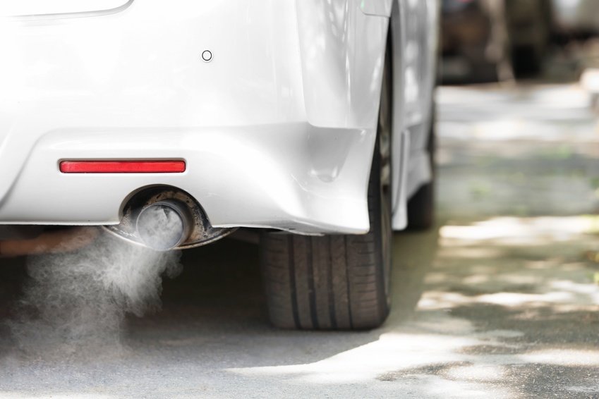
With some 40 million gasoline direct-injection (GDI) engines expected to be sold by 2025, it may be surprising to learn that these units emit more hazardous fine particulate matter than a port fuel-injected engine (PFI), or even the latest heavy-duty diesels equipped with a particulate filter.

The potential increase in the market means that GDI particulate emissions, though low compared to those of an unfiltered diesel, are now coming under scrutiny from regulators and manufacturers alike.

To reduce these emissions and improve overall performance engineers are studying new combustion designs and engineering concepts, including increasing the fuel pressure, alternate fuels and exhaust emissions control.

According to Matti Maricq, technical leader in chemical engineering and emissions after treatment at Ford’s Research and Innovation Center in Dearborn, injecting fuel directly into the cylinder enables a clean-burning explosion that wastes little fuel and delivers greater power.

During this process gasoline is sprayed directly where the combustion chamber is the hottest (rather than in the air intake), allowing for a more thorough, even and leaner burn.

Cleaner burning GDIs emit harmful particulates.

But because of incomplete fuel volatilization, partially fuel-rich zones and the “wetting” of piston and cylinder surfaces, GDI engines produce unwanted particulate matter. Most emissions typically occur during cold start and high load transient conditions during the warm-up phase, but this can vary according to load, drive-cycle phase and driver demands.

While “green” critics remain sceptical about so-called “engine management” methods, believing them to be unreliable compared to exhaust filters, most OEMs and component suppliers expect that combustion design and engineering changes will prove more cost-efficient and eventually equally effective.

Current development indicates that higher fuel pressure, possibly touching on 40MPa,together with new ultra-precision injectors will greatly improve future GDI systems. To further optimise the system engineers will also continue to improve injector timing, targeting, metering and atomization.

In a recent study, published by the SAE, it was established that an increase in fuel system pressure improved the homogeneity of the mixture and reduced the tip diffusion flame thereby significantly reducing particulate emissions under homogenous combustion in a GDi engine.

Furthermore, as a result of the enhanced intake charge motion at fuel pressures of between 20 MPa to 40 MPa a further reduction of particulate emissions was achieved.

As indicated by the combustion data, an increase in fuel pressure has a significant impact on the reduction of combustion emissions as well as improving fuel consumption.

However for a GDi system to operate optimally it’s important that, during the design and testing phase the pressure of the fuel in the common rail (CR) is correctly measured so that the ECU can be mapped accordingly.

Measurement of CR fuel pressure is key to lower particulate emissions.

Direct injection pressure is measured with sensors, and the signals are used to determine pump speed and/or volume.

Most direct injection systems use piezo-resistive pressure sensors on the low side of the system. The silicone chip element generates a measurable electrical voltage when pressure is applied, increasing as pressure increases.

On the high-pressure side sensors usually use a metallic membrane on a resistance bridge. When pressure is applied, the bridge generates a change in resistance that results in a change in the applied voltage. The Electronic Control Module (ECM) transforms the voltage into a calculated pressure, generally to within a ±2% accuracy.

To maintain the correct pressure, the ECM pulses the low-pressure pump. The system typically has a regulator and no return lines. Some systems even have integrated temperature sensors in the lines that are used to calculate the density of the fuel so that the fuel trim can be tuned to the amount of energy in the fuel.

To ensure accurate measurement of the line pressure it’s important that high precision pressure transmitters are used to map the pressure within the CR under all engine and load conditions. Any errors in this process can result in incorrect modulation of CR pressure which in turn can result in serious abnormalities, such as cylinder wash which can occur if the CR mean pressure exceeds the injector design pressure when fuel delivery is increased at high loads.

Additionally, with the introduction of the harmonized driving cycle OEMs will be under renewed pressure to meet emissions targets set by regulators, and GDI spark ignition engines will be at the forefront of a new generation of green technologies. However, for this technology to meet upcoming legislation particulate emissions need to be reduced, largely through the accurate control of the CR fuel pressure.
Pressure measurement technology in tire manufacturing

Pressure measurement technology in tire manufacturing

Every year, over one billion tires are manufactured worldwide. This sector thus counts among the biggest consumers of natural rubber. To give this natural material its correct shape and durability, high pressures and temperatures are necessary. No problem at all with the correct measurement technology.

Those believing that tire manufacture is a simple process, where the raw material is merely brought into a round form, are mistaken. In modern tire production, numerous individual components come together, which provide for both drive comfort and safety.

Tire manufacture – The first steps towards blanks

The manufacture of the raw material differs from one manufacturer to another and even from one tire type to another. Over forty different raw materials can be used here, including natural rubber, but also carbon black, sulfur and others. The various materials are kneaded together under extremely high temperatures. This mix is then stretched in length and ready for further processing upon cooling.

Using this mixture, the individual layers of the tire are produced. Other materials also come into use here, such as the rubber covered steel mesh in the belt, which stabilizes the tire and provides for increased cornering force. Further components of a tire include the carcass, bead, tread, sidewall, filler and inner liner.

The individual layers of a tire are brought together in a tire-building machine. These versions are termed blanks or “green tires.”

From blank to finished tire

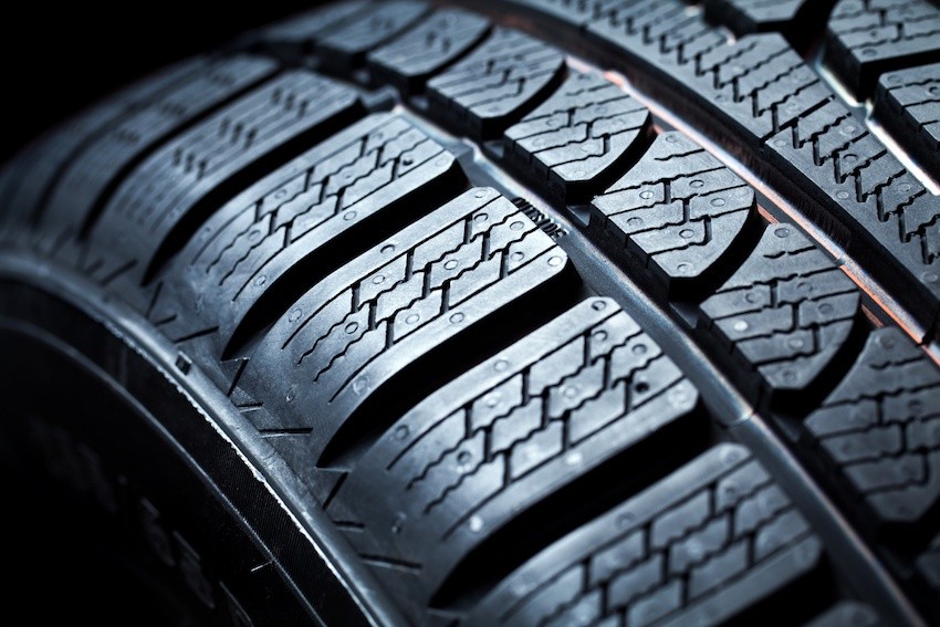
In the next step, the blanks are inserted into the vulcanization press.  At this point, the individual tire components are vulcanized together and the material then attains its required elastic consistency. To achieve vulcanization, the blank is “baked” in the press at a determined pressure and at high temperature.

During this process, the rubber bladder is inflated from within the inside of the press and forced outwards under pressure into the mold. This is how the tire profile is created. Temperatures reach up to 180°C here and pressures of over 24 bar can arise. This blowing pressure is monitored by various prestigious tire manufacturers using the ATM Sensor made by STS.

Vulcanization only with high-performance pressure transducers

With heat, steam and high pressures, harsh conditions are at play in tire manufacture. A pressure transmitter is thus required which can monitor, also at high temperatures, the pressures arising and can withstand the demands over a longer time. The transmitters of the ATM series are predestined in this scenario. Their high precision, reliability and outstanding long-term stability, as well as their compact and resilient design, provide for efficiency. In particular, their outstanding qualities during test and burst pressures prevent costly downtime. Furthermore, these pressure transmitters can easily be calibrated anew on-site.

MaP sensors are key to clean engine performance

MaP sensors are key to clean engine performance

In the face of ever tightening Global emissions regulations the motor industry has rapidly adopted clean technologies to reduce harmful Greenhouse gases. Critical to the operation of modern clean-burn engines is the precise control of air-fuel ratios (A/F) to stoichiometric values to attain high catalytic converter efficiency and minimize tailpipe emissions.

In order to optimise the A/F ratio under transient conditions manufacturers employ both closed and open loop systems:

  • A closed-loop system is one in which a signal proportional to the A/F is generated by an exhaust gas oxygen sensor (EGO), also known as a Lambda sensor, located in the exhaust stream.
  • An open-loop, or feedforward system controls injector fuel flow through signals received from an air flow meter.

In both cases signals are fed back through a digital PI controller to regulate the fuel injection pulse width. However these systems have two significant drawbacks:

  • Due to the relatively long delay inherent in the induction-compression-power-exhaust cycle of the engine the feedback, or closed-loop portion of the A/F control system, is only fully effective under steady-state operating conditions.
  • A reliable EGO sensor signal is only available after the sensor has warmed up, and thus closed-loop A/F control is not possible immediately upon starting the engine.

Hence, under transient and cold start conditions, the feed forward portion of the A/F controller is particularly important.

To optimise the A/F under all conditions modern engines are commonly fitted with a Manifold air Pressure (MaP) sensor to measure air pressure in the intake manifold.

The MaP sensor knows just what the engine needs

The MaP sensor continually measures the air pressure, and sends this information to the engine ECU, which inserts the data into a table which is used to control the Injector Pulse Width and Ignition Timing. These pressure readings are relayed to the ECU as output voltage signals.

During the development phase it is critical that the pressures measured in the manifold are accurate. Series production MaP sensors, whilst excellent at feeding signals to the ECU, often have wider tolerances than deemed acceptable for development: Therefore high quality pressure transmitters, such as those produced by STS, are commonly fitted in tandem to the series MaP sensors during the development phase. The readings obtained from these sensors are used to measure any deviations or errors when recording manifold pressures at various throttle openings.

The process is quite complex and requires that output voltages are measured at hundreds of throttle opening points, in order for the engine ECU to create an effective map of the engine’s requirements.

Using the Map sensor to teach the engine ECU

During the development phase, using a calibrated MaP sensor, the manifold pressure is measured at small throttle opening increments and the output voltages recorded against each setting.

At idle, with the throttle partially open, this pressure is measured at around 1/3 of atmospheric pressure, or 0.338Bar in a normally aspirated engine. Since the output voltage of the map sensor is proportional to the increase in pressure, the output voltage at idle will be approximately 5/3 = 1.67V where the nominal full scale output is 5V.

However, in practice, the full scale output of a production map sensor can vary and is usually less than 5V. This is because ofvariations among sensor manufacturers, with the result that a typical full scale voltage is around 4.6V. Because of these variances, during normal operation the map sensor reading will vary between about 1.5 V and 4.5V, with the exception of the vacuum created on the overrun where output voltages of less than 1V can be recorded.

Furthermore, since barometric pressure has a significant impact on the fuel mixture the ECU must also understand what the barometric pressure is. To accomplish this ambient pressure measurements are typically recorded just before the engine is started, just after it is turned off or both.

These measurements are usedto set a baseline condition which corrects the manifold pressure for weather and elevation conditions. In practice this is achieved using ignition-on and engine-off signals. This way, the same sensor that controls the engine while it is running is used for the barometric measurement when the engine is off.

Forced induction turns up the pressure on MaP sensors

When a naturally aspirated engine is converted to forced induction through the addition of a turbo or supercharger, the manifold pressure range has to be extended to include the boost region as well as the vacuum region. In order to cover the full pressure range, a map sensor must be used that covers at least 1.5 bar of pressure or a range that matches the engine design parameters.

Should boost pressures exceed 1.5 bar it’s important that, in order to maintain a full scale reading, a decreasing offset is added to the reading as pressure increases. This has practical importance because in map sensor based engine management systems, it is easy to hit-fuel cut or generate a fault in the ECU if the nominal full scale reading is surpassed. That is why a decreasing offset is mapped when a 2 bar sensor is used to read pressures above the nominal full scale pressure.

Sourcing MaP sensors to effectively meet these wide ranging requirements is not always easy. However, with the MaP sensor playing a crucial role in the effective management of the combustion process it’s important that, in order to accurately record manifold pressures during development, a precisely calibrated high quality MaP sensor is used. And with manufacturers under pressure to further reduce emissions and improve performance, application engineers will continue to demand improvements in the accuracy of the sensors used for development.

Measuring the heartbeat of the IC engine

Measuring the heartbeat of the IC engine

As a doctor measures blood pressure to determine the health of a patient, so too, the development engineer measures crankcase pressure to gain an insight into the condition of an engine on the test-bed. Not only does an increase in pressure provide an early indication of wear, but pressure measurement is crucial in the development of modern positive crankcase ventilation systems, that need to comply with emissions regulations.

It’s important to note that the measurement of crankcase pressure is not a direct measurement of “Blowby”, which is measured as a flowrate in standard cubic meters per second.

Measuring crankcase pressure to monitor cylinder liner, piston and ring wear.

Development engines are not cheap, taken that there’s usually an intensive engineering design program behind them: Therefore, the last thing any engineer wants to see is the test literally go up in smoke. To minimize the risk, testbeds nowadays are instrumented with a myriad of sensors to monitor everything from oil pressure and ambient temperature to EGTs and of particular interest, crankcase pressure.

Crankcase pressure sensors used on testbeds are particularly interesting as, not only are they capable of measuring relatively minor variances in pressure, but they are also stable across a wide temperature range whilst withstanding submersion in hot oil: This is particularly important as the sensor is often fitted to the sump or oil filler tube where it comes into direct contact with hot engine oil.

The piston-rings-cylinder (PRC) system is subjected to extreme stresses such as high frictional and accelerative forces, as well as extreme temperatures and pressures resulting from the combustion process.

Under these conditions there will always be some form of scavenging back into the crankcase, but as component wear increases, so will the pressure inside the engine. This is the basic principle behind measuring crankcase pressure as an early indication of wear on engines running on dynamometers or testbeds.

This increase of pressure in the crankcase in forced induction CI engines can be catastrophic, as the return of oil from the compressor will often be restricted resulting in the labyrinth seal failing causing a total loss of lubrication to the bearings.

Notwithstanding the importance of monitoring the PRC system’s condition, optimizing positive crankcase ventilation through accurate measurement of internal pressure is vital in meeting emissions legislation.

Designing the PCV for a cleaner environment.

In the early 1960s, General Motors identified crankcase gasses as a source of hydrocarbon emissions. They developed the PCV valve in an effort to help curb these emissions. This was the first real emissions control device fitted to a vehicle.

Ideally, the crankcase pressure should be controlled to just above atmospheric so that there’s enough pressure to exclude dust and moisture, but not enough to force oil past seals and gaskets; or on a forced induction engine, restrict the return of oil to the sump.

The first step in the design of an effective PCV valve is to determine the actual pressure in the crankcase by using a high quality pressure sensor specifically designed to accurately measure small differentials, whilst providing accurate repeatable readings across a wide temperature range.

Armed with the data accumulated during performance and durability runs, engineers are able to determine the appropriate parameters for the PCV valve:

  • Suitable cross sectional area to facilitate sufficient vapour flow from the crankcase
  • Correct operating pressure parameters to ensure unrestricted oil return on turbocharged engines, whilst retaining positive internal pressure.

Finally the prototype valve is evaluated on a testbed, again with crankcase pressure sensors fitted, to confirm performance and durability, as well as emissions compliance.

This development can span weeks and account for a sizeable chunk of the development bill, so the last thing a manufacturer would want is the failure of a vital sensor; which would require a partial, or even complete retest. That’s why OEMs only use high quality pressure transmitter, such as those produced by the pressure transmitter and transducer manufacturer STS.

As the “Cool War” hots up, so the pressure increases

As the “Cool War” hots up, so the pressure increases

Sustainable automotive air conditioning has been the subject of a heated debate over the past few years: The debate, nicknamed the “Cool War” has focused on the next-generation refrigerant to be used in car air conditioning.

The Alliance for CO2 Solutions and its supporters, scientists, NGOs and business leaders, have advocated that the motor industry replaces global warming chemical compounds such as R134a, with the natural refrigerant, carbon dioxide (CO2, R744/ R-744).

The change, they argue, will reduce vehicle pollutants by 10%, and cut total greenhouse gas emissions by 1% worldwide. If CO2 Technology is applied in other sectors, such as commercial and industrial refrigeration, heat pumps for water heating, etc. it may even eradicate up to 3% of the world’s greenhouse gasses.

However, the opposition’s juxtaposition also has merit: Refrigerants such as the Greenpeace-developed ‘Greenfreeze’, based on purified butane/propane mixtures, are entirely ‘natural,’ and due to increased efficiency over refrigerants such as R134a, allow for tiny amounts of refrigerant to be used.

And, the use of pure hydrocarbon refrigerants, which are ‘backward compatible’ with earlier Freon (R-12) car air conditioning systems, would allow these systems to be easily converted, increasing their efficiency, and preventing further release of harmful R-134a and R-12 into the atmosphere.

Unlike the Greenfreeze and hydrocarbon based air conditioners, motor vehicle air conditioner systems that run on R744 require a complete redesign to cope with pressures in excess of 100 Bar. Existing system components such as seals, hoses, valves and even compressors were never designed to operate under these conditions. And to make matters worse, the EU decreed that R134a be discontinued by January 2017.

Fortunately, there is another alternative: DuPont and Honeywell have already developed Hydrofluoroolefin (HFO)-1234yf in response to the 2006 EU directive requiring all new vehicles sold in the EU be equipped with low global warming potential (GWP) refrigerants. The limit was set at a GWP value of 150, which R1234yf meets easily. Further, it decomposes in the atmosphere in about eleven days, and the Life Cycle Climate Performance calculation, a model, certified by the US Environmental Protection Agency, confirms it’s one of “the most sustainable refrigerants for worldwide use.”

However, there is growing concern over the flammability of R1234yf; even prompting Mercedes-Benz to install a dedicated “cooling system” to dowse engine hotspots in the case of an accident that may lead to the evacuation of the A/C system.

With the notable exception of the E and S class, all new Mercedes-Benz vehicles will convert to R1234yz refrigerant from January 2017: The E and S classes will be the first series production vehicles fitted with the COair conditioning systems.

The reason that these top end models are equipped with CO2 charged air conditioners first, is because of the development time and cost to re-engineer the complete systems and effectively test them.

The extremely high system pressure and optimized component packaging required extensive qualification of the system. Of particular concern was the performance of the condenser, evaporator, pipes and hoses, and seals under the significantly higher operating pressures.

During development, accurately measuring the line pressure with pressure transmitters at critical points in the air conditioner was crucial in ensuring the integrity of the system; a drop in pressure would be an early indication of a component such as a seal failing, thus requiring a redesign. Accurately measuring pressure drop over the evaporator was also important to verify the design parameters and efficiency of the component.

However with most of the elements in the system having “shrunk” in size, placing a pressure sensor exactly where it was required was never going to be easy. Nevertheless, by using quality piezoresistive pressure sensors during development the problem was quickly overcome and the project was able to be completed in time to meet the January 2017 rollout.

Braking systems work best under pressure

Braking systems work best under pressure

Although some high-end vehicles are moving away from hydraulically activated braking systems to hybrid brake-by-wire versions, most drivers still rely on hydraulic pressure to bring them to a stop.

Even though vehicles have been equipped with hydraulic braking systems for decades, developing a system that delivers feedback to the driver whilst retaining effective retardation at all times and under all conditions is extremely challenging.

During the operation of the system there are several variables that all impact on performance:

  • The transfer of weight from the rear axles to the front axles, which requires a gradual modulation of pressure to the loaded wheels
  • The “knee-point”1) at which the servo reduces the assistance as well as the ratio of assistance versus pedal effort
  • Due to the pressure being applied, the pipes and hoses tend to expand and reduce line pressure for a given pedal travel (In extreme cases the driver may describe this as a “spongy pedal”)

1) The servo, or brake booster, provides a progressive assistance up to the knee point where the maximum vacuum assistance is received and any rise in output pressure beyond this point is only due to an increased pedal effort. If assistance was not reduced at this stage wheel-lockup would occur.

It should also be noted that with the introduction of multi-channel ABS many of the dynamic issues around wheel rotation and dynamic vs static friction have been taken care of, including pressure modulation due to the weight transfer under braking.

However the rapid cadence braking with the ABS engaged can create wildly fluctuating, and at times, extremely high line pressures which need to be determined, using high quality pressure transmitters strategically placed in critical lines, during development.

With operating line pressures in the region of 100 Bar it’s imperative that all components, including pipes and hoses, are designed to meet these pressures; and that the system does not exceed these specified values.

However this is also not that simple, when one considers that pipes and hoses of different cross sectional areas, with differing wall thicknesses could all produce similar braking performance, but some may be marginal on burst strength.

The only way this can be verified is through the accurate measurement of the line-pressure when the system is fully pressurized. Obviously these measured values must fall within the pipe and tube suppliers specifications.

Furthermore, it’s also important to measure line-pressure to confirm that the pedal leverage ratio can pressurize the system to about 80 Bar under severe braking conditions. If the desired pressure cannot be easily attained the pedal ratio must be increased until this pressure is achieved.

And when engineering the system engineers also need to select the correct master cylinder bore: One of the most common misconceptions is that a larger master cylinder will create more pressure. While a larger master cylinder creates a larger displacement, it takes more force to create the same pressure compared to a smaller bore.

While a larger master cylinder will take up system slack with less pedal stroke, it will take more force to create the same system pressure. The result after adding a larger master cylinder is a harder pedal which needs much more pedal pressure to create the same amount of braking force. For instance, moving from a 3/4″ master cylinder to a 1″ requires 77.7% more force on the push rod.

The objective in optimizing brake performance can only be achieved by balancing the entire system: Pedal force, system pressure and lever travel all need to be taken into account, and during the design and development phases manufacturers have come to rely on highly accurate pressure transmitters produced specifically for applications such as these.

Subscribe To Our Newsletter

Join our mailing list to receive the latest news and updates from our team.

You have Successfully Subscribed!