Hydrogen: source of hope

Hydrogen: source of hope

Pressure transmitters with gold-coated stainless steel diaphragms master special gas pressure measurements

Many experts are seeing hydrogen as the ideal substitute for coal, oil and natural gas in industry and transport, as it leaves practically no exhaust gases when burned. This versatile element is already used successfully in various industrial sectors. However, the handling of hydrogen gas puts high demands on the technical components used, and specifically on pressure transmitters.

The energy transition gets another pillar with hydrogen – in addition to renewable energies and energy efficiency. Hydrogen produced with renewable energies is a sustainable, flexible and easily transportable energy carrier. In addition to the German government’s current support programs, seven billion euros are invested to ensure that hydrogen becomes established on the market. A further two billion have been allocated for international partnerships. The focus is on so-called green hydrogen, which is produced exclusively with renewable energy. Only by means of green hydrogen, the CO2 emissions can be reduced using low-carbon energy sources. In Europe, 9.8 million metric tons of hydrogen are currently produced annually using mostly fossil fuels. Therefore, the EU Commission has set itself the goal of increasing the production of clean hydrogen to one million tons per year by 2024 and to ten million metric tons by 2030.

The production process of hydrogen

Hydrogen occurs in nature in combined form and is not easy to obtain. If it is used as a gas, the combination of hydrogen and oxygen has to be split up. But this electrolysis process, which chemically separates hydrogen and oxygen, requires a lot of energy. If electricity from solar plants or wind turbines is used, it is called “green hydrogen”. If the electricity comes from fossil fuels, the resulting hydrogen is called “gray hydrogen”.

Hydrogen is already used on a large scale by industry. In this case, however, it is not used as an energy carrier, but primarily in basic chemistry and petrochemistry in the context of stoichiological production processes. The hydrogen used in these applications is mainly referred to as gray hydrogen, which is produced by electrolysis processes or mostly as a by-product, e.g. in refineries.

Pressure sensors for hydrogen: what needs to be considered?

Regardless in which way hydrogen is produced and used, the handling of this element is very demanding in terms of technical solutions. Above all, working with hydrogen in its gaseous state is a challenge. Hydrogen is the element with the lowest density and the smallest atomic radius. This results in a fundamental problem in the handling of the gas: its extremely high permeation rate. Metallic materials are permeated by hydrogen, which has a negative effect, for example, on the use of pressure sensors. Piezoresistive transducers operate with an oil-filled housing with a thin steel diaphragm. If the hydrogen diffuses through this membrane and it accumulates in the transducer, the latter will be damaged or even destroyed in the long term. In the worst case, the hydrogen can even penetrate the entire sensor, creating an acute explosion hazard.

“Even doubling the thickness of the membrane leads at best to a doubling of the diffusion time,” knows our expert, founder of STS Sensor Technik AG. “However, the standard gold coating of the stainless steel membranes of our pressure transmitters in contact with hydrogen allows us to increase the time until a critical volume of hydrogen is reached in the transducer by a factor of 10 to 100. In this way, we significantly increase both the safety and the service life of the sensor.” This is due to the fact that the hydrogen permeability of gold is 10’000 times lower compared to steel. 

Gold coating of the membrane – the slight difference

STS develops, manufactures and sells application-specific solutions in pressure measurement technology – from the manufacturing of the individual parts to the calibration of the sensor and the final inspection of the end product. The applications range from machine and plant engineering to maritime applications, gas applications, life sciences and hydrogen applications. In applications, where the media to be measured has a significant hydrogen content, STS company uses gold-coated stainless steel diaphragms. Thereby, a significant optimization of the service life can be achieved. 

How does it work?

The permeability of gold is about 10,000 times lower than that of stainless steel. With a 1μm gold coating on a 50 μm steel membrane, hydrogen permeation can be reduced more effectively than by doubling the membrane thickness to 100 μm. In the first case, the time to reach a critical volume of hydrogen gas accumulated inside the pressure sensor can be increased by a factor of 10 to 100, in the second case only by a factor of two. The prerequisite for this is a completely closed system and a defect-free coating.

The piezoresistive pressure transmitter ATM.1ST  is suitable for static and dynamic pressure measurement in hydrogen applications. Its measuring ranges are between 0 … 50mbar and 0 … 1000 bar, the accuracies range up to 0.05%FS, hysteresis and repeatability are better than 0.01%. Due to its modular design, the pressure transmitter ATM.1ST can be individually adapted to many applications.

ITER International Thermonuclear Experimental Reactor for nuclear fusion

ITER International Thermonuclear Experimental Reactor for nuclear fusion

What is ITER?

ITER (“The Way” in Latin) is one of the most ambitious energy projects in the world today.

In southern France, 35 nations* are collaborating to build the world’s largest tokamak, a magnetic fusion device that has been designed to prove the feasibility of fusion as a large-scale and carbon-free source of energy based on the same principle that powers our Sun and stars. The ITER Members—China, the European Union, India, Japan, Korea, Russia and the United States—are now engaged in a 35-year collaboration to build and operate the ITER experimental device, and together bring fusion to the point where a demonstration fusion reactor can be designed.

ITER will be the first fusion device to produce net energy. ITER will be the first fusion device to maintain fusion for long periods of time. And ITER will be the first fusion device to test the integrated technologies, materials, and physics regimes necessary for the commercial production of fusion-based electricity.

WHAT WILL ITER DO?

1) Produce 500 MW of fusion power
The world record for fusion power is held by the European tokamak JET. In 1997, JET produced 16 MW of fusion power from a total input heating power of 24 MW (Q=0.67). ITER is designed to produce a ten-fold return on energy (Q=10), or 500 MW of fusion power from 50 MW of input heating power. ITER will not capture the energy it produces as electricity, but—as first of all fusion experiments in history to produce net energy gain—it will prepare the way for the machine that can.

2) Achieve a deuterium-tritium plasma in which the reaction is sustained through internal heating
Fusion research today is at the threshold of exploring a “burning plasma”—one in which the heat from the fusion reaction is confined within the plasma efficiently enough for the reaction to be sustained for a long duration. Scientists are confident that the plasmas in ITER will not only produce much more fusion energy, but will remain stable for longer periods of time.

3) Test tritium breeding
One of the missions for the later stages of ITER operation is to demonstrate the feasibility of producing tritium within the vacuum vessel. The world supply of tritium (used with deuterium to fuel the fusion reaction) is not sufficient to cover the needs of future power plants. ITER will provide a unique opportunity to test mockup in-vessel tritium breeding blankets in a real fusion environment.

WHAT IS FUSION?


Fusion is the energy source of the Sun and stars. In the tremendous heat and gravity at the core of these stellar bodies, hydrogen nuclei collide, fuse into heavier helium atoms and release tremendous amounts of energy in the process.

Twentieth-century fusion science identified the most efficient fusion reaction in the laboratory setting to be the reaction between two hydrogen isotopes, deuterium (D) and tritium (T). The DT fusion reaction produces the highest energy gain at the “lowest” temperatures.

Three conditions must be fulfilled to achieve fusion in a laboratory: very high temperature (on the order of 150,000,000° Celsius); sufficient plasma particle density (to increase the likelihood that collisions do occur); and sufficient confinement time (to hold the plasma, which has a propensity to expand, within a defined volume).

At extreme temperatures, electrons are separated from nuclei and a gas becomes a plasma—often referred to as the fourth state of matter. Fusion plasmas provide the environment in which light elements can fuse and yield energy.

In a tokamak device, powerful magnetic fields are used to confine and control the plasma.


WHAT IS A TOKAMAK?

Visualization courtesy of Jamison Daniel, Oak Ridge Leadership Computing Facility

Power plants today rely either on fossil fuels, nuclear fission, or renewable sources like wind or water. Whatever the energy source, the plants generate electricity by converting mechanical power, such as the rotation of a turbine, into electrical power. In a coal-fired steam station, the combustion of coal turns water into steam and the steam in turn drives turbine generators to produce electricity.

The tokamak is an experimental machine designed to harness the energy of fusion. Inside a tokamak, the energy produced through the fusion of atoms is absorbed as heat in the walls of the vessel. Just like a conventional power plant, a fusion power plant will use this heat to produce steam and then electricity by way of turbines and generators.

The heart of a tokamak is its doughnut-shaped vacuum chamber. Inside, under the influence of extreme heat and pressure, gaseous hydrogen fuel becomes a plasma—the very environment in which hydrogen atoms can be brought to fuse and yield energy. The charged particles of the plasma can be shaped and controlled by the massive magnetic coils placed around the vessel; physicists use this important property to confine the hot plasma away from the vessel walls. The term “tokamak” comes to us from a Russian acronym that stands for “toroidal chamber with magnetic coils.”

First developed by Soviet research in the late 1960s, the tokamak has been adopted around the world as the most promising configuration of magnetic fusion device. ITER will be the world’s largest tokamak—twice the size of the largest machine currently in operation, with ten times the plasma chamber volume.


WHEN WILL EXPERIMENTS BEGIN?

ITER’s First Plasma is scheduled for December 2025. 

That will be the first time the machine is powered on, and the first act of ITER’s multi-decade operational program.

ITER Timeline

Dec 2025                    First Plasma

2025-2035                  Progressive ramp-up of the machine

2035                            Deuterium-Tritium Operation begins

We invite you to explore the ITER website for more information on the science of ITER, the ITER international collaboration and the large-scale building project that is underway in Saint Paul-lez-Durance, southern France. 

STS provides high precision pressure sensors for this specific application.

CTD (Conductivity, Temperature, Depth)

CTD (Conductivity, Temperature, Depth)

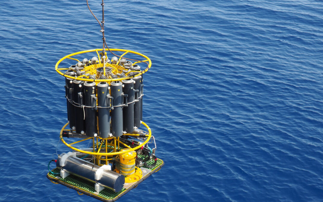
A CTD – an acronym for conductivity, temperature, and depth – is the primary instrument used to determine the essential physical properties of seawater. It provides scientists with an accurate and comprehensive representation of the distribution and variation of water temperature, salinity, and density to understand how the oceans affect life.

How it works.

The CTD on board consists of a set of small probes attached to a large metal rosette wheel. The rosette is sunk to the seafloor via a cable, and scientists monitor water properties in real time via a data cable that connects the CTD to a computer on the ship. A remote-controlled device allows the water bottles to be selectively closed during the ascent of the instrument. A standard CTD takes between two and five hours to collect a complete data set, depending on water depth. Water samples are often collected at specific depths so scientists can learn about the physical properties of the water column at that particular location and time.

Small, low-power CTD sensors are also used in autonomous instruments:

A moored profiler makes repeated measurements of ocean currents and water properties up and down through almost the entire water column, even in very deep water. The basic instruments it carries are a CTD for temperature and salinity and an ACM (acoustic current meter) to measure currents, but other instruments can be added, including bio-optical and chemical sensors.

Spray Gliders roam the ocean independently, running pre-programmed routes and surfacing occasionally to transmit collected data and accept new commands. As they cruise horizontally through the ocean, internal bladders control their buoyancy, enabling them to navigate up and down through the water column like whales and other marine animals.

Floats are floating robots that take profiles or vertical series of measurements (e.g., temperature and salinity) in the oceans.

Autonomous Underwater Vehicles (AUV’s) are programmable, robotic vehicles that, depending on their design, can drift, drive, or glide through the ocean without real-time control by human operators. Some AUVs communicate with operators periodically or continuously through satellite signals or underwater acoustic beacons to permit some level of control.

What platforms are needed?
A variety of other accessories and instruments may be included with the CTD package. These include Niskin bottles that collect water samples at various depths to measure chemical properties, acoustic Doppler current profilers (ADCP) that measure horizontal velocity, and oxygen sensors that measure dissolved oxygen levels in the water.

Features of the CTD’s sensors

  • Saltwater resistant
  • High accuracy
  • Lightweight
  • Low power consumption
  • Will be used at depths up to several thousand meters

Comments:
The small low power CTD sensors used on autonomous instruments such as water column profilers, spray gliders, floats and AUV’s are more complex to operate. The main limitation is the need to calibrate the individual sensors. This is especially true for autonomous instruments that are deployed for extended periods of time. (Ship CTDs are referenced to water sample data, which is generally not available for autonomous instrument deployments). Therefore, sensors must be stable for the deployment period, or assumptions must be made about seawater properties and referenced to the data. Deep water properties are typically very stable, so autonomous sensor data are matched to historical water properties at depth.

STS provides high precision pressure cells for this specific application.

More info about this customized product

Hydrogen effect on piezo transducers (bio fouling)

Hydrogen effect on piezo transducers (bio fouling)

BIOFOULING

Biofouling or biological fouling is the accumulation of microorganisms, plants, algae or animals on wetted surfaces, devices such as water inlets, pipework, grates, ponds and of course on measuring instruments, causing degradation to the primary purpose of those items.

ANTIFOULING

Antifouling is the process of removing or preventing these accumulations from forming. There are different solutions to reduce / prevent fouling processes at the ship hulls and in sea or brackish water tanks.

Special toxic coatings that kill the biofouling organisms; with the new EU Biocide directive many coatings were forbidden due to environment safety reasons.

  • Non-toxic anti-sticking coatings that prevent attachment of microorganisms on the surfaces. These coatings are usually based on organic polymers. They rely on low friction and low surface energies.
  • Ultrasonic antifouling. Ultrasonic transducers may be mounted in or around the hull on small to medium-sized boats. The systems are based on technology proven to control algae blooms.
  • Pulsed laser irradiation. Plasma pulse technology is effective against zebra mussels and works by stunning or killing the organisms with microsecond duration, energizing of the water with high voltage pulses.
  • Antifouling via electrolysis
  • Organisms cannot survive in a copper ions environment.
  • Copper ions occur by electrolysis with a copper anode.
  • In most of the cases, the tank housing or the ship hull serves as cathode.
  • A copper anode installed in the configuration generates an electrolysis between the anode and the cathode.

Hydrogen can appear due to ballast water treatment systems (electrolysis and UV-systems).
Gap corrosion caused by collection of chlorine between O-ring and body of the sensor can be
avoided by use of titanium sensors.

EFFECT OF ELECTROLYSIS ON THE PIEZO RESISTIVE TRANSDUCER

  • A result of the electrolysis are positive hydrogen ions
  • Because of their polarization, the hydrogen ions move towards the cathode (tank housing or ship hull) where the transducer is installed.
  • In case of direct contact between tank and transducer, the hydrogen ions will permeate through the thinnest component of the anode, which is the diaphragm of the transducer.
  • After permeation of hydrogen ions through the diaphragm, the hydrogen ions grab an electron and transform into molecular hydrogen (H2). The hydrogen accumulates in the fill fluid of the transducer.
  • If this effect lasts for a longer period, the concentration of hydrogen in the fill fluid will increase and the diaphragm will be bloated. As a result, the sensor drifts and issues an incorrect value.

Research results according to a laboratory for Material Science

Stainless steel pressure transmitters used during 2-3 years in ballast tanks of ships were investigated.
For this application, the sensor should be made of a more corrosion-resistant material such as
titanium.
By using titanium, we also prevent gap corrosion caused by clorine

RECOMMENDATION

According to this findings, STS Sensor Technik Sirnach AG has been successfully using piezo-resistive elastomer-free sensors with housing and membrane in titanium for applications in marine, brackish water and sea water applications for over 10 years.

More information about the application

More info about the product

Test fixture pressure sensors – Pressure measurement in the aircraft engine compartment

Test fixture pressure sensors – Pressure measurement in the aircraft engine compartment

As many engineers have found to their chagrin, dealing with pressure measurements in the engine compartment of an aircraft can be a delicate and frustrating experience. The heat, vibrations, orientation, and a multitude of other factors come into play. So how can we hope to develop a method for consistent and accurate readings? Well naturally, we’re left with hours, days, and most likely months of testing! However, we still need a test sensor that can rise to the occasion, function through all these changing conditions, and continually produce correct and repeatable results. We are engineers after all, and repeatable results are an occupational necessity. Thankfully for us, STS has stepped up to the plate to provide a complete series of pressure sensors to meet all of our testing needs. Where those needs can range from specific temperature requirements, size constraints, sealing material, and electrical output signals. All of these requirements will be covered in the following article as we address STS pressure transmitter usage for our testing needs.

Continuing with our engine compartment example, let’s zero in on the oil pressure. One of the first concerns while selecting a pressure sensor for this test is temperature resistance. Naturally, it gets quite warm next to an aircraft engine; therefore, we must ask ourselves, can the sensor be mounted alone or does it need a heat shield? More importantly, will the sensor even function properly when the components begin to heat up? Erratic oil pressure readings are very low on the wish list for a pilot! Therefore, both are valid points; but don’t fret too much. The STS line of pressure sensors include excellent temperature resistance, up to 125° C. This, in most cases, takes care of our initial temperature concerns and allows the sensor to be mounted it the most logical position in the engine compartment without the need to worry about temperature interference. Furthermore, we can fiddle, finagle, and fine-tune the test sensor’s location without constantly looking over our shoulder to see if the increased temperature will manipulate our results.  This provides us with a great deal of flexibility when constructing our test plan. 

Along the same subject of mounting locations, the size of the sensor is also crucial. Trying to wedge an ungainly box next to your sleek engine for a series of oil pressure tests would undoubtedly result in a few raised eyebrows amongst all those concerned. Additionally, space in this area is constantly at a premium. However, that is one bridge you don’t have to cross as STS has produced a very compact and low profile pressure sensor that makes for convenient mounting throughout your testing area of operations. Thanks to the advanced customization options, which we’ll discuss later, the exact dimensions vary from sensor to sensor. However, they tend to fall within the 50-60mm (2.0-2.4”) range. This small size allows for easy fixturing using common Adel clamps or any other off the shelf bracket without spending the time to design a custom mounting scheme, or trying to dream up a new overly complicated fixturing method every time the sensor has to be relocated to find the optimal position for oil pressure readings. All in all, this is certainly a time saver when we are focused on a timely and efficient series of tests.  

The last factor that we’ll touch on that can be invaluable for our pressure testing is customization. More often than not, the pressure sensors that are readily available on the market for such a test have a well-defined scope that they operate in. A single configuration that works best in ‘this’ pressure range, for ‘that’ frequency of collection, and it all comes with just ‘this’ product design. However, STS pressure sensors offer several options and customizations that give us the freedom to not limit our test based on our sensor’s individual capabilities.  

For our example, we of course must have a sealing material that with neither contaminate the oils, nor degrades with constant exposure. Well, we have several options for the sensor seals that can accomplish just that, including EPDM and Viton to ensure that the sensor is operating at peak performance for the entire test. Or, conversely, we can opt for a metallic sealing option to ensure proper test results. What’s more, perhaps we need a frontal diaphragm connection, with a PUR cable, along with 20 mA output signal. STS can deliver exactly that, along with any number of other combinations to ensure that the process connection, electrical and output signals, pressure connection, and seals are exactly what we need. In essence the sensor is cherry picked for our test and not simply some component we need to shoehorn into the test setup.  

To recap, we are required to design a series of oil pressure tests; and as with most tests, many of the factors will be manipulated. The heat, mounting method, pressure range and a mind-numbingly large number of other issues will all be changing constantly over the course of the test. To cap it all off, we need a test pressure transmitter that can fit into this envelope and consistently produce accurate results. Well we can at least nip that problem in the bud straight away by incorporating an STS pressure transmitter for our testing regimen. The high temperature and pressure ranges, combined with custom seals, process connections, electrical and signal outputs, and overall design ensure that this is a sensor that can pre-configured to slide seamlessly into your testing apparatus, and not require that your entire system by reconfigured to suit the sensor.

Cabin Pressure Testing

Cabin Pressure Testing

Proper cabin pressure is crucial in the aerospace industry. After all, a pilot rendered unconscious from lack of oxygen will not be overly helpful at the controls of a complex aircraft. Therefore, it falls to the engineers to develop a stellar cabin pressure system that will withstand even the most extreme conditions. To do that, we will of course be spending a great deal of time at the bench testing and re-testing every manifold, valve, and pressure vessel. So what do we need to create an effective and resilient cabin pressurization system? An effective and resilient pressure transmitter of course! In the following article we will cover many of the possible options and applications of the STS pressure sensors and how we can use them in this situation.

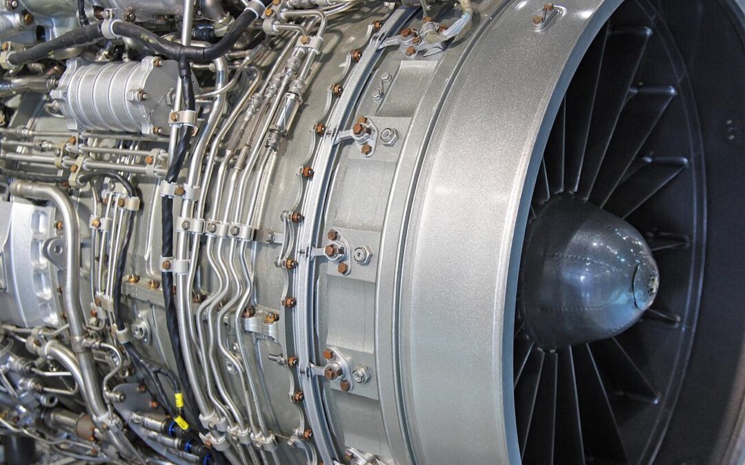
As we piece together our master plan for the cabin pressure test we will want to focus our attention on two critical factors; temperature resistance and overall accuracy. For our example, let’s move forward with a turbofan aircraft. As the air enters the engine, it is compressed by a series of rotors and a portion of this compressed air is diverted towards the cabin air system for the pressurization process. Now is the time to remember the compressible flow equations. As the incoming air is compressed, the temperature will also increase very quickly. Immediately after this initial compression the cabin air is transferred to a preliminary intercooler to shed a certain amount of that heat to the ambient air.  

As you can imagine, there is a great deal heat going into this area of our system. So naturally, if we wish to install a test pressure transmitter in this space to fine-tune, or verify, our cabin pressurization process, we’ll need one that includes an exceptionally high temperature resistance. Well, the STS line of pressure sensors offers us just that with a temperature limit of 150˚ C (302°F), where the sensor will continue to the function and transmit accurate data even in these  warm conditions. Furthermore, STS has adapted a fully customizable and modular approach to their design process to give us access to many more features in addition to superb temperature tolerance.  

Once the pressurized air has been cooled sufficiently, and its pressure recorded by our test sensor, the air can proceed to the primary manifold where the still warm air is mixed with colder atmospheric air to achieve a comfortable environment for the pilot. This is yet another crucial link in our cabin pressurization process, and it is therefore very likely to be equipped with a test sensor throughout the course of system testing. However, the conditions here are vastly different from those seen in the intercooler. Will the same pressure sensor even work here? The answer from STS is, YES! The wonderfully adaptable modular approach to the STS line of pressure sensors ensures that we will always be able to order a sensor to fit our needs.  

For our purposes, the manifold is one of the last stops for the air before it is passed along to the cabin. Therefore, accurate pressure measurements are crucial to ensure that the cabin is kept at standard ground level atmospheric pressure. With that in mind, we have the capability to select the most accurate variation of the sensor at ≤± 0.05% FS. This highly precise transmitter, the ATM.1ST model, will ensure that we the engineers have reliable and consistent data for this particular stage in our cabin pressurization sequence. 

While we’re on the subject of options and modules, STS also gives us the flexibility to select from a long list of possible electrical connectors and output signal types to ensure that each sensor is precisely assembled to our needs. This saves us from the painstaking process of redesigning a test fixture to the sensor’s needs. The standard connectors that we can readily choose from include PUR, FEP, and 5-pin M16 connectors. However, if this is not exactly what we need, STS does have the capacity to work with us to create an entirely custom connector, so there’s nothing to worry about!  

The last stop in our cabin pressure system that could do with a sensor during our testing project is the outflow valve. It is here that excess air is bled off into the atmosphere if we approach the point of over-pressurizing the cabin. Just like a test sensor in the manifold, accuracy is pivotal to ensure that we are maintaining the exact desired pressure in the cabin at all times, so once again the high precision ATM.1ST line would seem a logical starting point.  

Let us briefly reiterate the stops we made along our test plan. First, we have the intercooler which serves a fundamental role as the air moves towards the passenger compartment. Therefore, this location is also fundamental for our testing and requires a sensor that can register highly accurate data while at the same time resisting the high rate of temperature exchange in that particular area. Can the options available to us with the STS sensor accomplish this? Check. Next we moved to the manifold, or air mixing box, where accuracy and consistency are paramount. What’s more, a temperature transmitter would not go amiss in this area. Can we tackle this task through STS? Check. Last stop, the outflow value, where we once again need to precisely measure and record pressure data for our test, and again we can put a big check mark next to STS pressure sensors being able to keep up. All in all, the ATM.1ST pressure sensor has the potential to fulfill all our diverse testing needs throughout a dynamic and complex aircraft system, so stride forward confidently into the world of cabin air pressure!

Subscribe To Our Newsletter

Join our mailing list to receive the latest news and updates from our team.

You have Successfully Subscribed!