Deprecated: Hook wp_smush_should_skip_parse is deprecated since version 3.16.1! Use wp_smush_should_skip_lazy_load instead. in /home/xepoxenu/www/new.stssensors.com/wp-includes/functions.php on line 6078
Automotive Archives - STS Switzerland (EN)
Deprecated: Hook wp_smush_should_skip_parse is deprecated since version 3.16.1! Use wp_smush_should_skip_lazy_load instead. in /home/xepoxenu/www/new.stssensors.com/wp-includes/functions.php on line 6078
Pressure measurement of fuels – Material selection is decisive

Pressure measurement of fuels – Material selection is decisive

Aggressive liquids and gases pose a particular challenge to the pressure-sensing technology employed. For this reason, sensors are required which can be flexibly adjusted to the particular requirements. With the ATM.1ST product series, you will always remain on the safe side. 

A significant product characteristic of pressure transmitters is their modular construction. A variety of mechanical and electrical components can be co-assembled, according to application, to:

  1. optimally maintain the usage of matched pressure transmitters, and
  2. ensure a rapid implementation of the measurement setup.

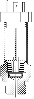
Figure 1: Assembly of a pressure sensor with O-ring measuring cell

The basis for this are high-quality measuring cells of a piezoresistive nature, which are sealed using O-rings. This construction allows for a multitude of combinations. Dependent upon usage within the pressurized medium, various O-ring materials are employed (Viton, EPDM or Kalrez) to optimally tailor the pressure sensors to that particular application.

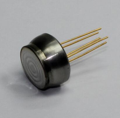
Figure 2: Example of a metal-seating pressure measurement cell

For application in aggressive media such as fuels (diesel, gasoline, …) or in high-pressure operations, however, sealing with O-rings becomes unsuitable. In such environments, the measuring cell has to be welded together with the pressure port. For this reason, an elastomer-free metal-sealing variant was developed for applications in fuels: The ATM.1ST product range.

These elastomer-free (metal-sealing) versions can be offered in the most diverse of mechanical designs. In the accuracy class of 0.05% FS, the pressure transmitter is available in nominal pressure ranges from 0…20  bar up to 0…100 bar and with an output signal from 4 – 20 mA.

In the 0.1% accuracy class, the pressure sensors are offered in nominal pressure ranges from 0…20 bar up to 0…700 bar and in versions of 4-20 mA or 0 – 5/10 V.

The analog transmitters are calibrated in two temperature ranges, -25…125°C (standard) or -40…125°C (optional). Across both temperature ranges, a Total Error Band of < 0.4% FS is guaranteed.

Featuring a shortened form, robust housing and a very high flexibility, the ATM.1ST product range allows end users to configure these pressure sensors according to the prevailing requirements. Regardless of pressure port or electrical connection, a broad range of possibilities for mechanical mounting are available.

With this convincing technical specification, these pressure sensors are ideally suited to various fields of application in measurement technology or plant and mechanical engineering, as well as in the equipping of test beds or calibration facilities.

Pressure measurement of fuels – Material selection is decisive

Minimizing pollutant emissions using pressure-sensing technology

Recall actions in the automobile industry have widespread consequences. Manufacturers have to contend with a huge image loss, as well as higher costs. Vehicle owners, on the other hand, react with anger and uncertainty. A particularly major stir has welled up over the past year with the scandal surrounding manipulated emissions figures. Politics has in turn reacted and signaled towards new testing procedures.

The automobile industry has triggered a true recall-crisis over the last two years. In the USA alone, some 51 million vehicles were ordered for recall during 2015 by the National Highway Traffic Safety Administration (NHTSA). This far exceeds the number actually sold in that same year, even though the vehicles recalled were not all connected to manipulated emissions figures. Some 11 million of these vehicles originate alone from the “Dieselgate” scandal involving the manufacturer Volkswagen. The losses involved are enormous.

Cost pressure and an increasing complexity of the systems built into vehicles are associated with heightened error susceptibilities and their resultant recall actions. This challenge is to be met primarily through improved and even more reliable control systems – on the part of manufacturers and suppliers, as well as government supervisory bodies responsible for legal specifications monitoring. High-grade measurement equipment is therefore needed, which can deliver the most precise of results under varying conditions and thus secure an optimal standards qualification (or post-qualification). A major backlog demand has since opened up in this respect.

The best pressure measurement technology for the best combustion engines

In the development of combustion engines, high-precision pressure transmitters are required, which, during combustion analysis, can facilitate the exact measurement of cylinder pressures, as well as intake and exhaust pressures. Absolute pressure sensors (gas exchange) and high-pressure sensors (injection pressure measurement) must also be of the highest-grade, since, in the latter instance especially, the potential for pollutant minimization is enormous. In this regard, particulates from gasoline engines can be reduced through an increase in injection pressure. Some suppliers are already working on increasing injection pressures to 350 bar or even higher.

Mobile emissions measurement is on the way

The standardized “New European Driving Cycle (NEDC)” is currently being introduced for exhaust and consumption measurements by state regulatory agencies. As we have witnessed, test procedures have given manufacturers all the freedom to influence measurements to their own advantage, since the vehicle is examined only in a test facility rather than under real-world conditions.

Once the manipulations became known, the Committee of Experts from the European Union decided in May 2015 that emissions during type approval are to be tested from late 2017 under practical driving conditions – known as Real Driving Emissions (RDE). The laboratory conditions for conventional checks will be supplemented by a procedure that prevents the use of cut-off devices during testing. The vehicle to be tested will be examined on an open track and thus subjected to variable conditions. Furthermore, random braking and accelerating procedures will also be performed.

Meeting new challenges – using modular pressure-sensor solutions

The RDE procedure obviously poses particular challenges to the measurement technology deployed. In the optimization of emissions figures for combustion engines, initial emphasis falls upon absolute and relative pressure measurement. With the new measurement procedures in mind, these need to perform reliably across a broad temperature range. Whether in the depths of winter or the heights of summer, measured values must be absolutely reliable to reflect a realistic picture of the true exhaust figures. It is also evident that operation at higher pressures can achieve significant reductions. For this reason, higher pressures must also be measurable. The fact that the pressure sensing technology employed operates without failure in mobile applications, given the new procedures, goes largely without saying.

Standard solutions cannot achieve this objective. Even more than that, they are actually part of the problem. Individual challenges require individual solutions. Also required are instruments that are precise as well as flexible enough to perform reliably in differing applications. Only by following this path can cost-efficiency and precisions be reconciled. It is clear that modular systems would be ideal in this context. In coordination with the manufacturer, these can be adapted to individual requirements and thus deliver highly reliable results. This represents a particular advantage in the development of new engines, since the adaptations can be made both straightforwardly and also promptly.

An experience that our customers have been making daily – and for almost 30 years now. As a leading manufacturer of customer-specific, modular measurement systems, we can provide tailored pressure measuring solutions within a short timeframe and in a proficient cooperation with manufacturers. Viewed from a measurements perspective, there exist no obstacles to the development of new, fuel-efficient engines, as well as to their testing under real-world practical conditions.

Miniaturization, increased efficiency, reduced consumption: Mobile air conditioning using carbon dioxide

Miniaturization, increased efficiency, reduced consumption: Mobile air conditioning using carbon dioxide

Carbon dioxide has been recognized as a refrigerant for over 150 years now. The fact that it is only now gaining entry into mobile air conditioning is due to lawmaker-applied pressure for reducing greenhouse gases and also to improved technical capabilities. Pressure measurement plays a central role in this latter process.

Fluorinated greenhouse gases with a Global Warming Potential above 150 have been forbidden by an EU directive since January 2011 in vehicle air conditioning. In the meantime, the common tetrafluoroethane refrigerant (R134a) has thus had to be used in substitution. Because CO2 is 1,430 times less harmful to the climate than R134a, it offers itself as an alternative due to its increased cooling performance and good chemical characteristics.

The arguments for CO2 as a refrigerant can no longer be dismissed.

  • As a naturally occurring gas, it enjoys both unlimited worldwide availability and cost-effectiveness.
  • It is far less damaging than other coolants, such as R134a, R404A, R407C and others.
  • Being a by-product of industrial processes, it has no need for expensive manufacture.
  • In contrast to other new refrigerants, it has already been well researched toxicologically.
  • It is neither toxic nor inflammable and thus represents a lower hazard risk than other materials.
  • It is also compatible with all other common materials.
  • It displays a very high cooling performance volumetrically and is also suited to heat pumps.

The switch from R134a to R744 (the abbreviation for CO2 in refrigerant form), however, cannot be simply implemented as is. Certain disadvantages stand in the way of its manifold virtues, which incidentally only apply in the case of constructing mobile air conditioners for vehicle use. A very high working pressure and its low critical temperature of 31°C are to be highlighted here. The conversion to R744 must therefore make a necessary detour via manufacturer test beds and those of their suppliers.

Air conditioning with CO2 – How it works

The operation of a common air conditioner begins, of course, with activation of an AC switch inside the vehicle. As a result, the magnetic coupling on the compressor is energized (although newer compressors have no magnetic coupling, with pressure being regulated internally by the piston stroke). A linkage between the pulley and compressor shaft is then established, with the compressor now drawing in the gaseous refrigerant. It now becomes condensed here and then forced into the high-pressure piping. In this process, however, the coolant temperature rises. The condenser built into the front end of the vehicle is responsible for lowering this temperature again. At this stage, the physical state of the refrigerant shifts from gaseous to liquid. The now fluid coolant is diverted to the receiver-dryer, where any moisture is removed. Next, the coolant is passed through the expansion valve. After passing this constriction, the refrigerant again alters its physical state inside the following evaporator. The energy required for this change is drawn from the ambient air, which in turn lowers the temperature within the vehicle interior. The gaseous coolant can now be drawn in again by the compressor, allowing the cycle to begin anew.

This cooling principle also remains the same for R744 application. The only difference is that the technical framework becomes somewhat altered. Because of its characteristics, carbon dioxide places other requirements upon the system in regard to pressure and temperature.

In comparison to a common mobile cooling system, the additional inner heat exchanger represents the biggest difference of all. This is essential because air conditioners using CO2 function with supercritical heat dissipation above 31°C. The cooling cycle proceeds as follows: The gas is condensed to a supercritical pressure inside the compressor. From there it enters a gas cooler, which performs the role of the condenser, when compared to common systems. The gas is cooled here, but no condensation takes place. A further cooling then occurs in the following heat exchanger. In the next step, the CO2 is pushed through the expansion valve, transforming the gas into a vapor form. This vapor portion is next evaporated within the evaporator, where the cooling-effect then takes place.

Apart from the inner heat exchanger and the gas cooler replacing the condenser, the high pressure essential to this system represents the biggest difference to previous mobile cooling systems. The demands upon the sturdiness of all components utilized increases in line with system pressure. This high pressure particularly influences compressor construction, which needs to be freshly designed as a result.

High pressures require high-performance measurement technology

A central aspect in the construction of new compressors is depicted by the very small molecular size of CO2, since it quickly diffuses through common sealing materials. An entirely freshly conceived shaft seal is thus required to prevent loss of cooling. This seal has to stand up to the refrigerant’s chemical characteristics and be able to withstand high compressor pressures in continuous operation – which can be determined during long-term testing on a test bed.

Even the compressor housing itself cannot be simply adopted from common cooling systems. To operate efficiently over the longer term, it must be able to withstand high temperatures. Heavily fluctuating suction pressures, which decisively influence drive chamber pressures, also represent a significant challenge. On the high-pressure side, maximal values can potentially attain a level of 200 bar. Because of these characteristics, leakages would occur much faster among common compressors than when operating using R134a. Compared to several years ago, a much more precise production of these components is possible today and this problem can now be overcome. A constant monitoring of pressures during prototype construction is therefore imperative.

The high pressures arising from climate systems using CO2 has further advantages beyond good environmental attributes and better cooling performance compared to R134a. Because of the higher density of CO2, the installation space needed is reduced in comparison to similar or even better-performing coolers using R134a. For the same cooling performance, only 13% of the volumetric flow of an R134a refrigerant compressor is required.

This reduction in size also reinforces the case for increasingly compact pressure measurement technology. Pressure sensors of a piezoresistive type offer themselves here due to their miniaturization capabilities, highly precise function at low pressures and even their exact results in the higher pressure ranges – in particular during long-term testing. The piezoresistive type of pressure transmitters from STS additionally offer manufacturers developing new models the decisive advantage that these instruments, thanks to their modular construction, can be quickly adapted to new requirements.

Mapping boost pressure on downsized turbo engines is the key to success

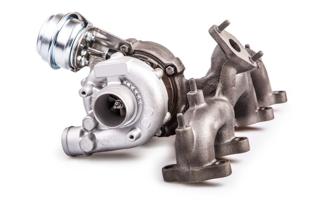
Mapping boost pressure on downsized turbo engines is the key to success

To meet ever tightening emissions legislation across the world OEMs are turning to downsized Spark Ignition engines. While these smaller engines consume less fuel and produce significantly lower emissions they require forced induction to deliver the performance drivers have come to expect from modern passenger vehicles.

The driveability of these downsized turbo engines must at least equal the performance of their naturally aspirated equivalents. This requires full boost pressure at low engine speeds without running out of steam at high speed, which can only be achieved with a sophisticated boost pressure control system.

The main problem with these forced induction spark ignition engines is the precise control of the air-fuel ratio near stoichiometric values at different boost pressures. At low speeds, these engines are prone to knock under medium to high loads.

Modern pressure control systems

Controlling the turbine-side bypass is the simplest form of boost pressure control.

Once a specific boost pressure is achieved, part of the exhaust gas flow is redirected around the turbine via a bypass. A spring-loaded diaphragm usually operates the wastegate which opens or closes the bypass in response to the boost pressure.

In recent times manufacturers have turned to variable turbine geometry to regulate boost pressure. This variable geometry allows the turbine flow cross-section to be varied to match the engine operating parameters.

At low engine speeds, the flow cross-section is reduced by closing the guide vanes. The boost pressure and hence the engine torque increases as a result of the higher pressure drop between turbine inlet and outlet. During acceleration from low speeds the vanes open and adapt to the corresponding engine requirements.

By regulating the turbine flow cross-section for each operating point the exhaust gas energy can be optimised, and as a result the efficiency of the turbocharger and therefore that of the engine is higher than that achieved with bypass control.

Today, electronic boost pressure regulation systems are increasingly used in modern Spark Ignition petrol engines. When compared with purely pneumatic control, which can only function as a full-load pressure limiter, a flexible boost pressure control allows an optimal part-load boost pressure setting.

The operation of the flap, or vanes, is subjected to a modulated control pressure instead of full boost pressure, using various parameters such as charge temperature, ignition timing advance and fuel quality.

Simulation reduces time to production and development costs

Faced with a plethora of complex variables, manufacturers have turned to simulation during the design and test phase.

A significant hurdle to overcome with downsized turbocharged engines is the narrow range within which the centrifugal compressor operates stably at high boost pressures.

The only way to build an effective simulation model is through extensive real world testing. This testing is mostly carried out on engine dynamometers in climatic chambers.

During wide open, and part throttle, runs the following pressure information is recorded:

  • Intake manifold pressure
  • Boost pressure
  • Barometric pressure

Of course this is all integrated with engine temperatures (Coolant and oil) to gain a picture of engine performance over the full engine speed range.

During this testing it’s important that engineers note any abnormalities in performance, as events such as exhaust pulses at specific engine speed can set up standing waves which can excite the impeller at a critical frequency which will reduce the life of the turbo, or even lead to catastrophic failure.

Therefore the measurement of pressure performance maps of both compressor and turbine is vital for the creation of an accurate extrapolation model for implementation during simulation.

A well-developed simulation tool can save the OEM time and money in dynamometer and road tests, but can only be developed once the pressure maps have been completed.

Landing gear hydraulic pressure testing

Landing gear hydraulic pressure testing

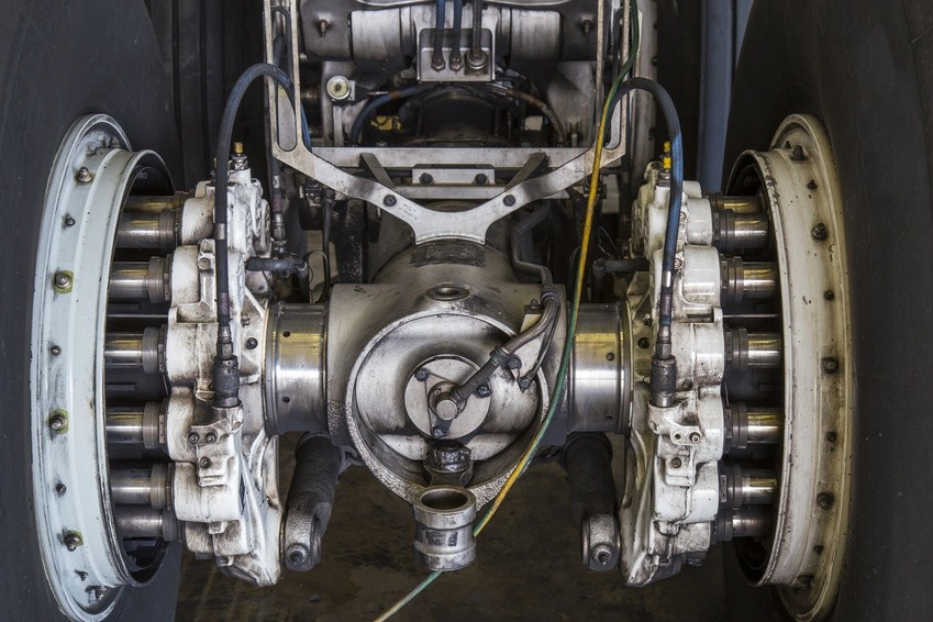
Imagine, you’re a pilot in your own plane, cruising on a beautiful day. You line up your approach to the airstrip and flip the switch to actuate the hydraulics for the landing gear to deploy. Suddenly, a low pressure warning appears and the landing gear won’t deploy. Now you have a problem! Amongst the grumblings under your breath will likely be a few unsavory comments about the engineers that designed that hydraulics system. Well, that’s us; and that pilot we’re imaging, that’s our client. They deserve to have a reliable and flawless landing, don’t they? Therefore, it’s on us to design a hydraulic system that can achieve just that, but how? Well the specifics, components, and design are across the board from plane to plane; however, there is one point that is guaranteed to be universal for our endeavors, hydraulic pressure testing! We will all test and test, then try to damage the system and test again! So naturally, we need a pressure sensor that can consistently and accurately record the conditions in our hydraulics system as we fine-tune all the details. Well we have a sensor that can do exactly that and for the remainder of this article we will explore the capabilities of the STS high precision pressure transmitter ATM.1ST.

As we begin to develop our hydraulic pressure measurement regimen, we must first determine the exact data we wish to collect. As we all know, ‘pressure’ is a very broad term to use in a hydraulic system and has very little meaning on its own. Are we referring to the accumulator pressure, pump delivery pressure, the regulator pressure, or perhaps the relief pressure? That decision is up to you, but thankfully STS has developed a series of pressure transmitters that can collect data in any of these sub-components. What do we mean by that? Well, the STS high-precision pressure transmitter ATM.1ST is designed with a modular and adaptable approach. We, as the engineers, can cherry-pick the features and capabilities for every sub-component of the sensor to ensure that every last one is perfectly suited for the environment that it will encounter over the course of the test.  

Let us now break down these sensor modules for a moment. First, we have our choice of materials for nearly every part of the sensor to ensure strength and durability. For example, the housing and transducer can be constructed from stainless steel or titanium depending on the burst pressure we must withstand amongst other factors, and this will in turn be determined from your particular hydraulic setup.  

However, our material selection is not limited to the housing. We also have the power to pick and choose the seal material for our sensor. The selections in this department include Viton, EPDM, Kalrez, and NBR. Naturally, the hydraulic fluid will be consistent throughout the landing gear system; therefore, once we determine the seal material that will have the best interaction with the fluid that particular material can be guaranteed to function throughout the system. Another factor to be kept consistent throughout our test setup is the overall accuracy of our pressure sensors. Luckily, STS grants us leverage over that characteristic as well with the high precision sensors of the ATM.1ST line. We have 0.25%, 0.1%, and 0.05% FS to ensure that our data collection is both accurate and consistent throughout the entirety of the test.  

The last two modular selections that are prudent to our landing gear testing are the electrical and process connections. In the electrical world we have FEP, PUR, and PE cables to select from, along with a range of different connectors. As for process connections, our diaphragm, DIN, and other specifications are entirely at our discretion. While the sheer volume of different combinations may seem slightly overwhelming at face value, they grant us the capability to piece together a pressure sensor that will slide into our test setup seamlessly without driving any special setup or design changes.  

Now let us return to our landing gear testing. As we develop and test the hydraulic system to achieve flawless landing gear operation we are going to need data from several locations within the system. As mentioned above, we have the accumulator that acts as a damping device of sorts to smooth out any pressure variations within the system. Naturally, we as the engineers need to know what those variations are exactly. Therefore this seems to be a perfect location for a test sensor!  

On the subject of pressure maintenance, the regulator also falls squarely into this category. As the pressure fluctuates due to valves opening and closing or any irregularities in the system, the regulator kicks in to ensure that the system pressure remains within the specified range. Once again, this is another crucial component to keep an eye on as we develop our landing gear, and we now have the resources to select a perfectly customized pressure sensor to slide into the system and accomplish just that with precise measurements and easy to install electrical connectors. 

In review, we are tasked to develop a reliable landing gear system via a rigorous curriculum of testing. However, the hydraulic system of such a mechanism is extremely diverse in terms of components and potential locations for sensors. Thankfully for us, STS has produced a reliable little powerhouse in the ATM.1ST pressure sensor that allows us to have nearly complete jurisdiction over all aspects of the sensor; including materials, accuracy, sealing, and electrical connectors. Long story short ladies and gentlemen, this high-accuracy sensor allows us to devise a streamlined and robust testing process where our test sensors complement our setup, and do not dictate it.

Pressure sensors in motorsport: Where a fraction of a horsepower is decisive

Pressure sensors in motorsport: Where a fraction of a horsepower is decisive

“The winner takes it all!” The world of motor racing is divided into winners and losers, with the successful driver enjoying the champagne shower. The preliminary outcome, however, takes place on the engine development test bed, with high-performance pressure sensors representing the decisive competitive advantage.

STS supplies pressure sensors to customers from the world of motorsport, including participants in Formula 1 and NASCAR. Both of these racing series, despite all their differences, have one thing in common. Every horsepower counts and embodies the decisive advantage on the track. When every tenth of a horsepower is to be wrestled from extensive analysis on engine testbeds, the end results have to be absolutely reliable down to last decimal place.

Pressure measurement technology in Formula 1 engine development

The current engine regulations in Formula 1 were introduced in 2014. V-layout engines of six cylinders, 1.6 liters displacement and a single turbocharger are driven. The rev speeds reach up to 15,000 min−1. The Kinetic Energy Recovery System (KERS), an electrical system for recovering energy under braking first introduced in 2009, has now been replaced by the Energy Recovery System (ERS). In modern Formula 1, the engines involved are thus of a hybrid type. The future of Formula 1, for this reason, has long since become the present. The perhaps most successful racing series worldwide is also a testing laboratory for the road. From disc brakes to computer diagnostics, many technologies now found in everyday road traffic have their origins in the development centers of Formula 1.

The prevailing engine regulations, which evenly delineate the parameters for all teams, make thorough research on the testbed essential to carving out the decisive advantage. Every single horsepower counts. In comparison to tests for vehicles in normal road traffic, different requirements, to some extent, are applied. Oil and water pressures are higher, as are their arising temperatures. When improved fuel economy and increased performance is the aim, then extensive testing under racing conditions is essential. Furthermore, the precision of measured results across the required temperature range is of great significance. In Formula 1, major leaps in terms of horsepower are often not the case – improvements even in the decimal regions are a reason for celebration at this elevated performance level.

In light of these challenges, a well known racing team from Formula 1 approached STS, since the hitherto employed sensor technology failed to meet their high requirements. The measuring instruments used were too big and too heavy. Even more serious, however, was the problem that additional cooling technology had to be built into the testbed, since the sensor temperatures would otherwise rapidly escalate above the maximum. Measured results under this scenario would thus be worthless.

The aim of the developers was to acquire pressure sensors that permit standardization and make additional cooling elements obsolete. The topics of weight and size also play a role, since these factors influence the performance of the speeding car.

STS provided the racing team with a new sensor from the ATM series, available on the market from the fall of this year. This sensor scored not only in its desired precision across the required temperature range, but also delivered a further decisive advantage which could enduringly optimize engine development. With the previously used sensors from another manufacturer, there were malfunctions when switching to the hybrid systems employed since 2014. The results were that the testbed would shut itself down and longer term measurements were practically impossible. The ATM sensors from STS are fail-safe and thus allow for extensive testing on the road to the victory podium.

Pressure measurement technology in NASCAR engine development

Although hybrid engines are not built into NASCAR stock cars, extensive testing is still required to attain the optimum in performance. In this sport also, a well known engine manufacturer has opted for the pressure measurement technology from STS. During extensive tests, some 200 ATM.1ST pressure transmitters have been keeping an eye on oil, water, fuel and air pressures. From air pressures reaching the engine right through to improvements in oil flow, the aim is to precisely examine various factors to attain even the slightest increase in performance (involved here is ca. 900 PS). As with Formula 1, the highest of precision is required. The scope here amounts to just a tenth of a horsepower!

The manufacturer choice went to the ATM.1ST pressure transmitter, since it is largely unrivalled in its required performance characteristics.

  • The modularity of STS sensors also allows the manufacturer to connect a special pressure adapter.
  • A total error of ≤ ± 0.30 % FS permits meaningful analyses for improving engine performance.
  • Long-term stability considerably minimizes the need for calibration.
  • The pressure measuring range from 100 mbar…1,000 bar is well suited to those pressures arising during engine development.
  • Outstanding temperature compensation allows for precise results across a broad temperature range – a decisive criteria for the sharply rising temperatures during performance testing at these highest levels.

Whether in Formula 1 or NASCAR, the path to the victory podium leads through engine testbeds. In the high-performance motorsport field in particular, high-precision sensors are required for monitoring all of the important data from oil and water pressures to fuel and air pressures. Besides precision, fail-safe capability also plays an important role in being able to conduct essential long-term testing that yields reliable results.

Subscribe To Our Newsletter

Join our mailing list to receive the latest news and updates from our team.

You have Successfully Subscribed!