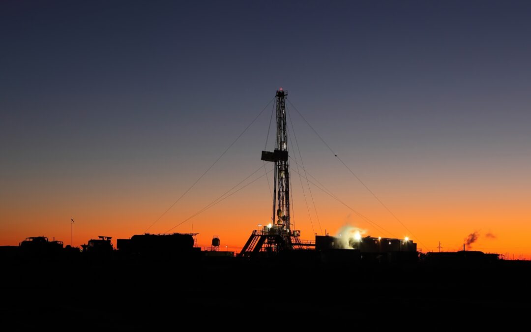
Pressure unlocks Compressed Natural Gas’ potential
Thanks to its very high energy density, compressed natural gas (CNG) is well suited for use as an automotive fuel. CNG has an octane number of approximately 120 and combustion heat of 9,000 to 11,000 kcal/ kg or 38 to 47 MJ/ kg.
In addition, the combustion of CNG produces significantly less CO2 emissions than does the combustion of gasoline, for example. And because CNG is a particularly cost-effective fuel in many markets, manufacturers are showing a growing interest in developing vehicles that are capable of running on this alternative fuel source.
The primary challenge in optimizing an Internal Combustion Engine to run on CNG is regulating the injection pressure in the fuel rail.

Image 1: Example of a two fuel system for gasoline and CNG
Image Source: Bosch Mobility Solutions
CNG is stored at approximately 200 Bar, and is commonly injected at between two to nine Bar, depending on the engine requirements – low pressure for fuel efficient driving in the lower speed ranges, and higher pressures when greater power and torque are required.
The effectiveness of combustion within an engine’s cylinder is strongly influenced by the temperature and pressure of the CNG: An increase in pressure at constant volume will result in higher mass density of the gas, thus increasing its heating value.
However, even though the initial temperature and injection pressure can be varied, if not accurately calibrated during development, compressed natural gas vehicles can suffer from power loss and poor drivability.
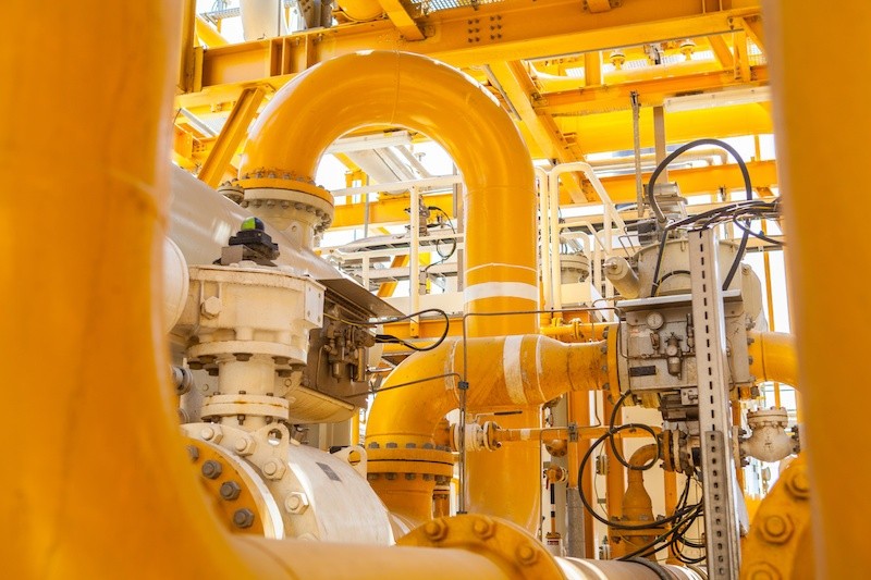
Injecting CNG under pressure
Typically, CNG is fed from a high-pressure tank via a pressure regulator to the fuel rail. For efficient fuel combustion, the amount of natural gas injected must always be matched to the mass of air required by the engine. To achieve this the electronic engine management typically employs an air-flow meter to determine the exact amount of air required and subsequently the quantity of CNG to be injected.
With central point injection (CPI), the CNG is fed from a natural-gas distributor (NGD) into the intake manifold. A medium-pressure sensor measures the pressure and temperature in the NGD, allowing the natural-gas injectors to deliver the precise amount of fuel required.
Alternatively, the injection can also be implemented without the NGD, by aligning each injector with a corresponding cylinder. With this multi-point injection (MPI), the gas is injected under pressure at each cylinder’s intake manifold ‘runner,’ upstream of the intake valve.
Because changes in pressure have a significant influence on the engine’s performance when running on CNG fuel, engine torque and exhaust emissions (CO, CO2, NOx and hydrocarbons) all have to be recorded during engine testing.
Optimizing rail pressure for all driving conditions
To optimize the CNG system it’s important that during the design and testing phases the pressure within the rail is accurately measured at various throttle openings and cross referenced to engine torque and the corresponding exhaust gas emissions. Consequently high quality pressure sensors are demanded by most development engineers.
It’s important that these sensors deliver accurate readings across a wide range of pressures, while retaining their integrity at elevated temperatures.
Although an increase in CNG pressure reduces CO2, HC and NOx, CO in the exhaust gas increases, making it vital to accurately record the effects of modulating the CNG injection pressure.
During testing a pressure regulator is used to control injection pressure which is measured by an accurately calibrated pressure sensor located in the rail, while an analog flow meter, typically with a capacity of 2.5 m3/ h,is used to measure and control the inlet air flow rate. A chassis dynamometer is used to record engine torque.
For the duration of the test, gas temperature and flow rate are kept constant at 22°C and 0.1 SCFH, respectively. A high power blower is used to maintain engine temperature during the test, and emission test equipment is attached to the exhaust outlet to record CO, CO2, hydrocarbons and NOx content in the exhaust gases.
The process is quite complex and requires rail pressure, torque and emissions to be measured at hundreds of throttle opening points in order to create an effective map of the engine’s requirements for the engine ECU.
Measuring, recording and inputting all this data into the relevant tables is a time consuming task, therefore development engineers often turn to modeling tools to fast-track development. These tools commonly provide an environment for simulation and model-based design for dynamic and embedded systems, thereby reducing the number of hardware versions required to design the system.
The simulation model is coded with the information gained from the real-time testing and then built into an executable using C compiler to run on a real time operating system.
Once the baseline data is captured it’s possible to generate an infinite number of real-time simulations to be applied to any facet of the design cycle – from initial concept, to controller design, test and validation using hardware-in-loop (HIL) testing.
A well-developed test program using laboratory grade pressure sensors and test equipment unleashes performance and drivability from CNG fueled vehicles that is comparable to fossil fueled equivalents, while delivering cost and emissions benefits.