Deprecated: Hook wp_smush_should_skip_parse is deprecated since version 3.16.1! Use wp_smush_should_skip_lazy_load instead. in /home/xepoxenu/www/new.stssensors.com/wp-includes/functions.php on line 6078
Pressure Measurement Archives - STS Switzerland (EN)
Deprecated: Hook wp_smush_should_skip_parse is deprecated since version 3.16.1! Use wp_smush_should_skip_lazy_load instead. in /home/xepoxenu/www/new.stssensors.com/wp-includes/functions.php on line 6078
Pressure peaks in hydraulic systems: A risk to sensors and other equipment

Pressure peaks in hydraulic systems: A risk to sensors and other equipment

Pressure peaks occur in virtually all gas and liquid-filled pipelines. Those pressures arising in just a few milliseconds can exceed the overload pressure of the pressure transducers employed and also destroy them.

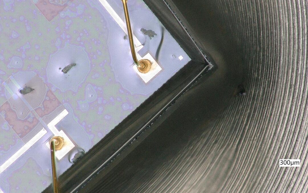
Pressure peaks, or very high pressures existing over a short timeframe, are usually noticed only when the damage has already been done. They are the result of pressure surges and also other physical phenomena (cavitation, micro-diesel effect) that occur wherever liquids or gases are transported through pipes. Pressure peaks, however, are less important among gases due to their high compressibility and thus only rarely represent a danger. In the context of water pipes, the term ‘water hammer’ is often used. With these terms, a dynamic pressure change of the liquid is ultimately implied. When, for example, a valve is quickly closed, water flow will stop instantaneously. This triggers a pressure wave, which flows through the medium against the direction of flow at the speed of sound and is then reflected back again. Within milliseconds, there is a sharp pressure increase which can cause damage to pressure sensors and other equipment (damage to pipe fittings and pipe clamps, as well as to pumps and their footings etc.). In the first line, however, it is the measuring devices that are affected, upon which we will be concentrating in the following. These damages can appear as a tiny “rupture” or a deformation (see Figures 1 and 2).

Figure 1: “Rupture” as a result of pressure spike

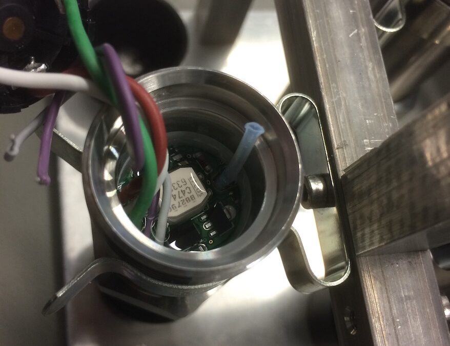
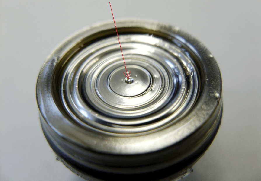
Figure 2: Deformations due to pressure peaks

If the pressure acting on the pressure transducer exceeds the overload pressure, then this will sustain permanent damage. There are two possible scenarios here: As paradoxical as it may sound, the complete destruction of the measuring instrument due to pressure peak is the mildest of consequences. Users, after all, do notice the damage immediately here. If the sensor is merely deformed as the result of a pressure peak, however, it will continue to operate, but deliver only inaccurate measurements. The financial consequences here are disproportionally higher than with a totally destroyed sensor.

How to prevent damage caused by pressure peaks

The golden path to preventing damage caused by pressure peaks lies in the integration of pulsation dampers or pressure chokes. Other means, such as the use of valves, would not lead to satisfactory results, because they are too slow to react to pressure peaks which actually arise in mere milliseconds.

The purpose of a choke is to dampen pressure peaks so that they no longer exceed the overload pressure of pressure transducers and then damage them. For this purpose, the choke is placed in the pressure channel in front of the sensor cell. As a result, pressure peaks will no longer reach the membrane directly and unchecked, since they must first pass through the choke itself:

Figure 3: Pressure channel with Pressure choke

Because of their very good protection from pressure peaks, the use of pressure chokes remains the best option. This variant, however, does have its pitfalls. It can lead to a blockage of the pressure channel due to calcification and deposits, especially in media with solid and suspended particles. This results in a slowing down of the measurement signal. If chokes are used in relevant applications, then regular maintenance should be carried out here.

A supplementary protection from pressure peaks can be achieved with a higher overpressure resistance, as opposed to the standard one. Whether this is advisable depends upon the particular application: If high accuracy readings are required, these can no longer be achieved in certain circumstances of very high overpressure resistance relative to the measurement range.

Strain gauges in pressure measurement technology

Strain gauges in pressure measurement technology

Strain gauges are measuring devices that change their electrical resistance through mechanical deformation. They are used in a variety of measuring instruments, which, besides scales and load cells, also includes pressure sensors.

Pressure sensors rely on several physical variables, including inductance, capacitance or piezoelectricity. The most common physical property by which pressure transmitters operate, however, is the electrical resistance that can be observed in the metallic deformation, or piezoresistive effect, of semiconductor strain gauges. The pressure is determined by a mechanical deformation, where strain gauges are attached to an elastic carrier. It is important here that the strain gauges can follow the movements of this carrier. If a pressure acts on the carrier, the deformation arising brings about a change in cross-section of the conductor tracks, which in turn causes a shift in the electrical resistance. It is ultimately this change in electrical resistance that a pressure transducer records and from which the pressure can then be determined.

Figure 1: Strain gauges deform under pressure

The deformation acting upon the conductor will thus cause it to change in length (Δl). Since the volume remains the same, it is the cross-section and thus the resistance R that changes:

ΔR/R = k • Δl/l

The change in resistance (ΔR) is proportional to the change in length (Δl), and the proportionality factor (k) will depend on both the geometry and the material properties. While ‘k’ will be 2 for metallic conductors, it can also be very high in semiconductors. Because of these relatively high ‘k-factors’ for semiconductors, these are more sensitive and can therefore measure even the slightest of pressure changes. Temperature dependency, however, also increases as a result of this.

The change in resistance in metallic strain gauges results from dimensional changes (geometry). In semiconductor strain gauges, however, the change is due to alterations in the crystal structure (piezoresistive effect).

The evaluation of the resistance change triggered by a pressure-induced deformation then takes place via a bridge circuit. For this purpose, the strain gauges are connected up to form a Wheatstone bridge (Figure 2). Two of the strain gauges are placed in a radial direction and two in a tangential one. It is thus so that two become stretched and two become compressed under deformation. In order for temperature effects to be compensated and for the signal to be as linear as possible, it is important that the strain gauges have the exact same resistances and are arranged in an exact geometry.

Figure 2: Bridge circuit

Metallic strain gauges

Among metallic strain gauges, we must differentiate between the foil and thin-film varieties.

Foil strain gauges consist of rolled foil, only a few microns thick. Constantan is normally used as the material here, but Karma and Modco can also be employed, especially if a larger temperature range is needed or the temperatures are below -150 °C. Constantan has a very low ‘k-factor’ of 2.05 and is therefore not very sensitive. Considering this, the material displays a lowered temperature dependency, which is also why it is most often used in foil strain gauges.

Foil strain gauges are more likely to be used in load cells. Often they are not sensitive enough to be pressure transducers, since values of less than one bar cannot be recorded with them. Their temperature range is also relatively limited, and, depending on the version, temperatures of even 80 °C should not be exceeded.

Thin-film strain gauges are produced by the so-called thin-film technique, by, for example, vapor deposition or sputter coating. The manufacturing process is more complex here and also more expensive than for foil gauges. On the other hand, however, a temperature range of 170 °C is possible, with their long-term stability also being very good.

Metallic thin-film strain gauges provide for stable over the longer term, but also quite expensive, measuring instruments. It holds true that the lower the pressures to be detected are, the higher the manufacturing cost will be. Low pressures of less than 6 bar can only be detected at a poor accuracy.

Semiconductor strain gauges

Semiconductor strain gauges operate by the piezoresistive effect. The material used in most cases is silicon. Semiconductor strain gauges tend to be more sensitive than the metallic variety. They are also usually separated from the medium by a separation membrane, with the pressure being passed on via a transfer fluid.

Figure 3: Piezoresistive measuring device

In semiconductor materials, the piezoresistive effect is about fifty times more pronounced than with metallic strain gauges. The semiconductor strain gauges are either glued to a carrier or directly sputter-coated onto it. The latter enables an intense bonding and assures freedom from hysteresis, as well as a resistance to aging and temperature stability. Although the piezoresistive effect is not exclusive to the semiconductor strain gauge, the term “piezoresistive pressure sensor” has come to be used for instruments where the elastic structure deforming under pressure and the resistors are all integrated into one chip. Piezoresistive pressure transducers can be made small in size and (apart from the membrane) without any moving parts. Their production is based on normal semiconductor fabrication methods. At the same time, there is the possibility of integrating the resistors with the elastic membrane deforming under pressure all into one chip and thus produce a full pressure measurement cell in the size of just one chip.

Piezo thin-film strain gauges are attached to a silicon carrier and separated from the carrier by an insulating layer. This increases the manufacturing requirement and thus also the price, but temperature ranges from -30 °C to 200 °C are possible here. Thanks to the highly elastic properties of silicon, only a low hysteresis can be expected with these. It is the high ‘k-factor’ that achieves the high sensitivity, making piezoresistive pressure transmitters the first choice for the smallest of pressure ranges on the mbar scale. In addition, devices of tiny dimension can be produced, which has a positive effect on the scope of potential applications. Also, the long-term stability and EMC compatibility is very good, with the latter, of course, depending upon carrier material. Temperature compensation, however, requires a little more effort, but even this challenge can also be overcome quite easily. You can read more about temperature compensation here.

Thick-film strain gauges are printed onto ceramic or metallic membranes. With a thickness of 20 microns, they are up to 1,000 times thicker than thin-film strain gauges. Because of their low production requirements, these are cheaper in price, but not very stable longer term due to the aging of their thick film.

Summary: The type of strain gauge used has a major influence on the measuring instrument. Factors such as price, accuracy and long-term stability play an important role in choosing the right pressure transmitter. In our experience, pressure transmitters with piezo thin-film strain gauges have proven to be the most efficient, because, thanks to their sensitivity, they can record wide pressure ranges at high accuracy, whilst also exhibiting good long-term stability.

Mechanical simulation prior to demanding pressure measurement projects

Mechanical simulation prior to demanding pressure measurement projects

Engineering methods and modern technologies enable manufacturers to design pressure transmitters to meet practical requirements. This is especially essential for demanding applications.

The general conditions for the development of offshore oil fields are extremely difficult. Far from the mainland and at great depths, pressure transmitters are exposed here to high loads. Functional failure is extremely costly, since in the event of failure, the module has to be retrieved from the deep sea and then also reinstalled. It is essential to make reliable predictions in advance about unit functionality under the conditions to be anticipated. For this reason, the individual components of the pressure transmitter are first exposed to a mechanical simulation of the environmental conditions found in the deep sea.

Figure 1: FEM simulation of a sensor housing

The finite element method (FEM) is used in mechanical simulation. This is a common numerical process for examining the strength of bodies with a geometrically complex shape. The solid body to be examined, such as the housing of a pressure transmitter, is divided into finite elements, or partial bodies. This is therefore a physical modeling using computationally intensive software to determine whether the finite elements, and ultimately the overall structure also, would withstand those forces to be expected. Oil exploration is primarily distinguished by very high pressures. At a sea depth of 2,500 meters – by no means unusual in this field of application – a pressure of 250 bar is exerted upon the housing. In addition to this external pressure, the process pressure itself must also be taken into account, which can even be considerably higher (when pressure peaks occur, for example).

In the finite element method, therefore, no finished pressure transmitters are examined for their strength, but instead a modeling is performed as realistically as possible. If a solution is found that meets the specifications of the user, the product would then be tested out in an actual experiment, which will no longer be taking place virtually. In an individual pressure measurement solution for users in offshore oil production, this experiment in the pressure chamber is of primary importance. These hyperbaric tests validate the results of the finite element method and determine the load limit of the components or of the entire system. This ultimately ensures that users with special sensor requirements receive a product that performs reliably.

Figure 2: Micrographs of two sensor housings. Left: no pressurization. Right: after a hyperbaric test at 1,500 bar. No changes seen, the housing is stable.

Figure 2 shows the micrographs of two identical sensor housings. The housing shown on the left was not pressurized, whereas the right one was subjected to a pressure of 1,500 bar. This corresponds to a water column of 15 kilometers and thus much more than at the deepest point of the oceans. By optimizing the component using the finite element method, it can be modeled to withstand this enormous pressure. For comparison, the Mariana Trench is the deepest point of the oceans at 11 kilometers down. Pressure measurements taken even in the Mariana Trench itself should therefore pose no problems. The safety margin for most applications is thus very high and reliable operation is guaranteed.

Further applications of the finite element method

Mechanical simulations are not only useful for high-pressure applications. As already described elsewhere, temperature is an important influential factor in piezoresistive pressure measurement. Let us now take the exhaust pipe of a motor vehicle as an example. The temperatures here are very high and can exceed the limits of a pressure transmitter. In this application case, the finite element method would be used to investigate how the pressure transmitter must be designed so that no more than 150 °C of heat acts upon the measuring cell.

Mechanical simulations can also be useful in the low-pressure range. Mechanical changes, after all, have a much greater impact at low pressures. While measurement deviations in the mbar range are unlikely to be decisive in a high-pressure application, this is already a significant value for a measuring range below one bar. As an example, the connecting element between the measuring chip and the housing is usually an adhesive. If the torque is too high when mounting the pressure transmitter, this connection could be loosened or even just slightly altered and distortions would then be transferred to the measuring cell. This alone can lead to serious measurement errors. The properties of the adhesive used can also be modeled using the finite element method. The aim here, of course, must not be to find out the load limit of the connecting element and convey this to the user, but instead to find a solution that can easily withstand all possible torques applied during mounting.

The effort of mechanical simulations does pay off in the long run. Not only can products be designed to meet the required specifications, but this also allows for optimizing the design so that the products are as user-friendly as possible.

Fouling as a cause of drift in pressure sensors

Fouling as a cause of drift in pressure sensors

We all know the saying that ‘you can’t make an omelet without breaking eggs’. In the development of new combustion engines specifically, this means that soot particles or oil residue can contaminate the sensors employed.

The consequence of such soiling amounts to increasingly inaccurate readings. When, for example, the exhaust system of a new combustion engine is being monitored with pressure transducers, more and more fine dust will settle on the diaphragm of the sensor over time. The membranes of piezoresistive pressure sensors are very thin so that they can deliver high-precision measurement results. But when a layer of soot forms on this over time, it reduces the overall sensitivity of the pressure transducer.

Protecting pressure transmitters from particulate matter

End users make note of this drift in the sensor by performing reference pressure measurements. They will find considerable differences between the values of this reference pressure gauge and the soiled sensor itself. Often, however, the readings experienced by users reveal when the measured signals deviate too far from the expected results. Strong fluctuations in these measured values can also be an indicator of contamination.

STS generally recommends that users whose sensors are exposed to dirt should service them after a maximum of 100 operating hours. In addition, users can also try to protect the sensor as much as possible from contamination. There are two common methods used here.

Method 1: Protective foil

The first method does not replace maintenance of the sensor after a maximum of 100 hours, but it does simplify cleaning and also preserves the membrane. In this case, a very thin, metallic protective foil is applied to the membrane to protect it from soiling. After a maximum of 100 operating hours, this film is then simply peeled off and replaced with a new one.

Method 2: Cooling adapter

This method allows users to kill two birds with one stone. By screwing a cooling adapter or a climatic valve to the front end of the pressure port, the membrane is now largely protected from soiling. The climatic valve opens only when there is actually something to be measured. Where no permanent pressure monitoring is required, this can be a good method for minimizing the degree of contamination to the sensor employed.

At the same time, a constant sensor temperature can also be ensured via this cooling element. Besides membrane contamination, temperature also has an effect on the measuring accuracy of piezoresistive pressure transducers (More on the influence of temperature on the accuracy of pressure sensors can be found here).

Cleaning of pressure sensors from oil contamination

Contamination with heavy oil particularly comes about in the development of marine engines. The additives incorporated become especially deposited on the membrane and can even damage it. These residues reduce the sensitivity of the pressure transducer and regular servicing must be observed here also.

To keep soiling and the consequences thereof as minimal as possible, consideration should be given to the nature of the pressure sensor at its selection. A stainless steel membrane is recommended, which is front-flush and has no channels in which even the smallest of deposits can gather. The smoother the better also applies here, because on a rough membrane undesired particles will actually deposit faster and these are also more difficult to clean.

To clean a soiled pressure sensor, it must be removed from its application. Isopropanol (IPA) is recommended as the cleaning agent here. While the sensor housing requires no special caution, the membrane should be treated without any firm pressures by using, for example, cotton swabs. Under no circumstances should compressed air be used, since the membranes are very thin and, when too much pressure is exerted, deformations can occur.

Vibrations: The pressure sensor is also affected

Vibrations: The pressure sensor is also affected

In virtually all applications where compressors, turbines and motors come into play, vibrations are to be found, which also affect measurement sensors. Without appropriate precautions, this can impair the functionality of the pressure transducers employed.

The effects of vibration on pressure sensors can be serious: On the one hand, the measurement signal can be disturbed by superimposition. If this vibration is transmitted to the output signal, end users will not receive useful measurement results. This effect can be observed without any delay and a continuous load here can also lead to material fatigue. Welding seams can break apart and threaded connections become loose. Whether through distorted measurement results or broken mechanical connections, vibrations can render pressure sensors inoperable. Fortunately, these undesirable effects can also be largely minimized.

Preventing damage to the pressure measurement system by vibrations

Prevention is the best measure. This requires that users are aware of the vibrations occurring in the respective application. The first step is to determine the vibration frequency of the application. Vibrations do not cause damage per se. In manufacturers’ data sheets, the frequency range in which no interference occurs is often listed under “Tests”. The DIN EN 60068-2-6 standard is applied here, where the test specimen is subjected to a defined frequency range over a predetermined test duration. The aim here is to specify the characteristic frequencies of the test specimen. The actual test procedure is shown in Figure 1.

Figure 1: Qualification of a prototype: Pressure sensor is screwed into an aluminum block that is loaded mechanically (vibration, acceleration)

If strong vibrations arise that exceed the specifications of the pressure sensor, two approaches can be initially considered. The first is concerned with spatial dimension: How big is the pressure transducer and where is it installed? It holds true that the heavier and larger a pressure transducer is, the greater the effect of the vibrations and the lower the resistance. It may thus be advantageous in strongly vibrating applications to use a smaller pressure transmitter, such as the ATM.mini, which suffers little effect from vibrations due to its small mass.

Besides the dimensions of the pressure transducer, its actual position in the application is also decisive. If it sits along the vibration axis, then it will receive less vibration. When it is mounted across the vibration axis, however, it must be able to withstand the full extent of those vibrations.

In addition, the pressure transducer itself can be equipped to even better tolerate vibrations. For this purpose, the pressure transmitter is encased in a soft sealing compound, which dampens the vibrations and thus adequately protects the mechanical components. In Figure 2 this sealing compound is seen as transparently glossy.

Figure 2: Pressure sensor with sealing compound 

In summary, it can be said that strong vibrations could damage the measurement sensor. By selecting a pressure transmitter suitable for the application (frequency range, dimensions) as well as optimal mounting (along the vibration axis), the effects of any vibrations can be minimized. Further protection is provided by encasing the sensor in a dampening sealer compound (see Figure 2). 

The fundamentals of hygienic pressure measurement

The fundamentals of hygienic pressure measurement

The requirements on pressure transmitters are particularly high in the foodstuffs and pharmaceuticals industries, as well as in the biotechnology and related industries (the packaging and filling industry, for example). In the following, we will describe what end users in these industries must consider when choosing a suitable pressure transmitter.

The main focus in pressure measurement in the above industries is, of course, on hygiene. Contamination of the products and the propagation of germs must be prevented to protect humans and the environment. Pressure transducers used in sensitive environments must therefore comply with the regulations of the relevant authorities (Europe: EHEDG; USA: FDA). Besides the materials employed, the design of the pressure transmitters must also be observed.

Design of pressure transducers

Hygiene-friendly pressure transmitters must be easy to clean and germs must have an adequately small surface area to target. This begins with construction of the measuring instruments. Dead spaces, crevices and edges are thus to be avoided, since germs can accumulate at these points and cleaning made more difficult.

An equally important aspect is the connection. The pressure transmitters must be easy to dismantle, since frequent cleaning is to be carried out in sensitive applications, and the seals must be regularly changed. This circumstance generally rules out screw threads. But there is also a further reason independent of dismantling, being that screw threads provide impurities even more surface area to attack. For this reason, hygienic pressure transducers usually have milk flanges, clamp flanges and DIN flanges.

All components must be flush with one another and an efficient assembly and disassembly respected.

Materials of pressure transducers

The cleaning aspect is also the main focus of the materials employed. This starts with the surfaces of the selected materials. Both the membrane and other elements of the pressure sensor in contact with the medium should have the lowest possible roughness. The rougher a material, the more germs are able to adhere to it and the more difficult cleaning then becomes. A roughness of 0.8 μm is standard in hygienic applications, although not optimal for every process. To meet the highest requirements, a roughness of ≤ 0.4 μm should be considered.

Roughness, of course, is also caused by corrosion. For this reason, the housing material plays an important role in hygienic pressure transmitters. Only high quality stainless steels with a low ferrite content should be used in order to eliminate corrosion as much as possible. An example here is the material 1.4404, also known as V4A steel, which, due to its 2% molybdenum content, meets increased requirements for corrosion resistance. The EHEDG provides guidelines here for the suitability of construction materials in the individual processes concerned.

The requirement of smoothness, of course, also applies to the sealing materials, which must be chemically and thermally stable. If they are not, then they become porous over time and thus offer an ideal surface for attack. STS uses Viton for its hygienic pressure transmitters, a fluoroelastomer with high thermal and chemical resistance, which withstands hydrocarbons even at higher temperatures without swelling up or becoming porous.

The requirements for the materials employed are derived from the cleaning processes in the foodstuffs and pharmaceuticals industries, as well as from biotechnology. Pressure transmitters used in closed installations must be able to withstand Cleaning in Place (CIP) and Sterilization in Place (SIP) cleaning procedures. In these processes, installations are cleaned without any further disassembly. To make the demands on these materials clear, the CIP method itself should now be briefly described:

  1. In the first step, coarse contamination is removed by pre-rinsing with water.
  2. Next, an alkaline agent is used.
  3. This alkaline detergent is then rinsed away with water.
  4. To remove limescale and similar deposits, the installations are rinsed with an acid.
  5. The acid is now rinsed away with water.
  6. A disinfectant is then used to kill off microorganisms.
  7. A flushing with ultrapure water to finish off.

In the SIP process, steam is fed into the application at an average temperature of 140 degrees Celsius. The pressure transmitters must therefore be able to survive these corresponding temperatures without suffering damage.

One last aspect of material selection rests with the pressure transfer fluid. In “normal” pressure transmitters, silicone oils are often used. These, however, can contaminate the process media if the pressure transmitter is damaged. Beer, for example, would no longer froth, just to name one comparatively harmless example from the foodstuffs industry. Only those fluids listed by the authorities may be used here.

ATM/F – Hygienic Pressure Transmitter

Other aspects / special cases

While the above-mentioned aspects belong to a hygienic pressure measurement, there are two further points that may be of relevance to some users. This certainly includes explosion safety with ATEX certification. In addition, the possibility of readjustment, which most pressure transmitters no longer have, can also be an important cost factor. In particularly critical processes in the biotechnology or pharmaceuticals industry, the measuring instruments used must be validated every three months. If these can be freshly adjusted in a calibration laboratory, where appropriate, then this is an advantage not to be ignored.

A further special case might be the combination of both pressure and temperature measurement. For example, an STS customer needed temperature monitoring on a packaging machine for sterile injection needles in addition to the pressure measurement. When both applications can be combined within one hygienic instrument, then this minimizes both the space requirement and the cleaning effort.

This special case, however, also serves as an example for pressure measurement in sensitive environments, since users must conform to strict guidelines. And these can also differ from process to process (with regard to permitted materials, for example). Thanks to the modular design principle of STS, hygienic pressure transmitters can also be adapted to individual requirements within the very shortest of time.

Subscribe To Our Newsletter

Join our mailing list to receive the latest news and updates from our team.

You have Successfully Subscribed!