Pressure peaks in hydraulic systems: A risk to sensors and other equipment

Pressure peaks in hydraulic systems: A risk to sensors and other equipment

Pressure peaks occur in virtually all gas and liquid-filled pipelines. Those pressures arising in just a few milliseconds can exceed the overload pressure of the pressure transducers employed and also destroy them.

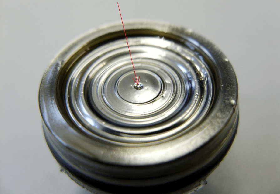
Pressure peaks, or very high pressures existing over a short timeframe, are usually noticed only when the damage has already been done. They are the result of pressure surges and also other physical phenomena (cavitation, micro-diesel effect) that occur wherever liquids or gases are transported through pipes. Pressure peaks, however, are less important among gases due to their high compressibility and thus only rarely represent a danger. In the context of water pipes, the term ‘water hammer’ is often used. With these terms, a dynamic pressure change of the liquid is ultimately implied. When, for example, a valve is quickly closed, water flow will stop instantaneously. This triggers a pressure wave, which flows through the medium against the direction of flow at the speed of sound and is then reflected back again. Within milliseconds, there is a sharp pressure increase which can cause damage to pressure sensors and other equipment (damage to pipe fittings and pipe clamps, as well as to pumps and their footings etc.). In the first line, however, it is the measuring devices that are affected, upon which we will be concentrating in the following. These damages can appear as a tiny “rupture” or a deformation (see Figures 1 and 2).
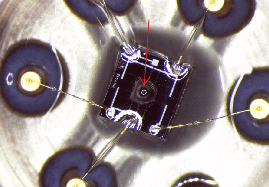
Figure 1: “Rupture” as a result of pressure spike

Figure 2: Deformations due to pressure peaks

If the pressure acting on the pressure transducer exceeds the overload pressure, then this will sustain permanent damage. There are two possible scenarios here: As paradoxical as it may sound, the complete destruction of the measuring instrument due to pressure peak is the mildest of consequences. Users, after all, do notice the damage immediately here. If the sensor is merely deformed as the result of a pressure peak, however, it will continue to operate, but deliver only inaccurate measurements. The financial consequences here are disproportionally higher than with a totally destroyed sensor.

How to prevent damage caused by pressure peaks

The golden path to preventing damage caused by pressure peaks lies in the integration of pulsation dampers or pressure chokes. Other means, such as the use of valves, would not lead to satisfactory results, because they are too slow to react to pressure peaks which actually arise in mere milliseconds.

The purpose of a choke is to dampen pressure peaks so that they no longer exceed the overload pressure of pressure transducers and then damage them. For this purpose, the choke is placed in the pressure channel in front of the sensor cell. As a result, pressure peaks will no longer reach the membrane directly and unchecked, since they must first pass through the choke itself:
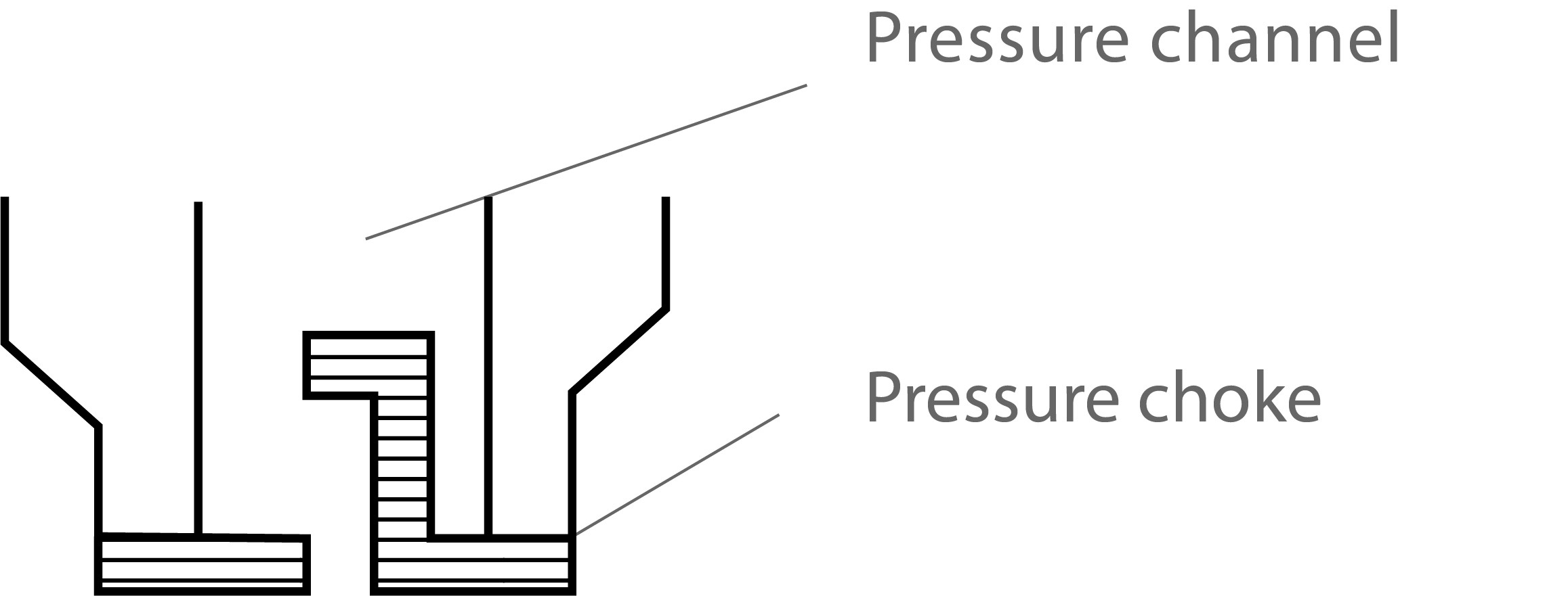
Figure 3: Pressure channel with Pressure choke

Because of their very good protection from pressure peaks, the use of pressure chokes remains the best option. This variant, however, does have its pitfalls. It can lead to a blockage of the pressure channel due to calcification and deposits, especially in media with solid and suspended particles. This results in a slowing down of the measurement signal. If chokes are used in relevant applications, then regular maintenance should be carried out here.

A supplementary protection from pressure peaks can be achieved with a higher overpressure resistance, as opposed to the standard one. Whether this is advisable depends upon the particular application: If high accuracy readings are required, these can no longer be achieved in certain circumstances of very high overpressure resistance relative to the measurement range.

Temperature compensation: The key to precision

Temperature compensation: The key to precision

When selecting the right pressure transducer, knowledge of the temperatures that may arise is of the utmost importance. If the measurement technology used is not adequately temperature-compensated, serious inaccuracies and other risks will be the net outcome.

This is why end users need to know in advance which temperatures are to be expected within their own specific application. There are two values to consider here: The media temperature and the ambient temperature. Both of these values are important. The media temperature is the value at which the pressure port makes its contact. The ambient temperature, however, is the value arising in the environment surrounding the application and ultimately affects the electrical connections. Both values can be very different from one another, yet each also has differing consequences.

Why is temperature an important factor?

The materials used in piezoresistive pressure transducers display a certain temperature dependency (read more about the thermal characteristics of piezoresistive pressure transmitters here). The measurement behavior of the pressure transducer thus also shifts with temperature. As a result, temperature-related zero offsets and span errors will now arise. Expressed in simple terms, if a pressure of 10 bar is approached at 25 °C and then for a second time at 100 °C, different measured values will be obtained. For users viewing a data sheet, this means that excellent accuracy values are really of little use when temperature compensation itself remains insufficient.

Apart from avoiding serious measurement errors, the mechanical functionality of the measuring instrument also depends upon the existing temperature. This mainly affects components such as electrical connections and the cables used for the transmission of measured values. Very few of the standard materials can withstand temperatures around, yet alone above, 100 °C. The cable sockets and cables themselves can melt or even catch fire here. Besides measuring accuracy, temperature also has an influence on operational safety.

Fortunately, users need not to live with these risks, since pressure transducers can be optimized for different temperature conditions – on the one hand through temperature compensation, and on the other using additional cooling elements and particularly heat-resistant materials.

Temperature errors can be avoided

The manufacturers of pressure sensors employ temperature compensation. Products from STS, for example, are optimized as standard for operating temperatures from -0 °C to 70 °C. The further the temperature deviates from these values, the greater the measurement inaccuracy becomes. A measuring instrument optimized for a range from 0 °C to 70 °C but used at temperatures around 100 °C will no longer achieve its specified accuracy values. In this case, a sensor must be deployed, which is actually compensated for temperatures of around 100 ° C.

There are two forms of temperature compensation:

  • Passive compensation: Temperature-dependent resistors are activated in the Wheatstone bridge
  • Active compensation (polynomial compensation): Various pressures are approached at rising temperatures within a heating cabinet. These are then compared with the values from a calibration standard. The temperature coefficients determined from this are next entered into the electronics of the pressure transmitter so that the temperature errors in actual practice can now be compensated for “actively”.

Active temperature compensation remains the preferred method because it leads to the most accurate of results.

Temperature compensation itself, on the other hand, does have its limitations. As previously mentioned, temperature affects not only the precision of a pressure transmitter. The mechanical components of the measuring cell also suffer at temperatures above 150 °C. At these temperatures, contacts and bondings can become loose and the sensor itself suffers damage. If exceptionally high media temperatures are to be expected, then additional cooling elements will be required to ensure the functionality of the sensor.

Cooling elements at very high media temperatures

To protect the pressure transmitter from very high temperatures, there are four variants which can be employed depending upon the application and the temperature involved.

Variant A: Media temperatures to around 150 °C

In this variant, a cooling fin element is integrated between the measuring cell and the amplifier. It is a matter here of separating the electronics from the actual application, so that these remain undamaged by the elevated temperatures.

Variant B: Temperatures above 150 °C

If the medium is very hot, a cooling element is screwed in front of the pressure port (cooling fins, for example, that can be screwed from both sides). The pressure port thus comes into contact now solely with the cooled medium. These forward-attached cooling fins have no effect at all on the accuracy of the sensor. Should the medium be extremely hot steam, however, then a siphon would instead be employed as the cooling element.

Variant C: Extremely high temperatures (up to 250 °C)

When the media temperature is extremely high, a forward-facing isolating system incorporating a cooling section can now be used. This variant, however, is quite large in size and does affect the accuracy negatively.

Pressure transducer with forward isolator and cooling section for media temperatures up to 250 °C

Variant D: Special case of a warming cabinet or climatic chamber

When pressure measurements are necessary inside a warming cabinet at ambient temperatures of up to 150 °C, the electronics of the pressure transmitter cannot be exposed to these temperatures without suffering damage. In this instance, only the measuring cell (with pressure port and stainless steel housing) is located within the cabinet, with this connected to the remote electronics outside the cabinet (also housed in a stainless steel housing) via a high-temperature FEP cable.

In summary: Consultation is king

The precision of piezoresistive pressure sensors is influenced by temperature conditions. The temperatures acting on the pressure port can be compensated for passively or actively so that the pressure sensor used meets the requirements upon accuracy over the anticipated temperature range. Furthermore, the influence of ambient temperature on the mechanical components of the measuring instrument must also be taken into consideration. Using forward-mounted cooling elements and heat-resistant materials, this can also be brought under control. Users should thus always rely on the comprehensive advice offered by the manufacturer and ensure that the pressure transducers available can be optimized to their very own specific applications.

Calibration of pressure transmitters

Calibration of pressure transmitters

Because of mechanical, chemical or thermal influences, the precision of a measuring device alters over the course of time. This aging process is normal and cannot be overlooked. It is therefore essential to recognize these alterations in good time by means of calibration.

The calibration of pressure gauges is important for various reasons. On the one hand, it is about adherence to established standards such as ISO 9001, to mention just one. Manufacturers, on the other hand, also gain very specific advantages, such as process improvements and cost savings (by using the correct quantities of raw materials, for example). This can prove very worthwhile, since a study performed by the Nielsen Research Company in 2008 shows that the costs of defective calibration to producing companies average 1.7 million dollars per annum. Furthermore, calibration must also be viewed as a central component of quality assurance. In some sectors, such as the chemical industry, consistent and error-free calibrations are also a factor relevant to safety.

Definition: Calibration, adjustment and verification

The terms calibration, adjustment and verification are often used synonymously. All three terms, however, contain significant differences. In the case of calibration, the display of the measuring instrument to be tested is compared to the results from a standard. The standard here is a reference device, the precise function of which remains assured. Using comparative measurements, each measuring device must be capable of being traced back to a national standard through a chain of comparative measurements (“traceability”). For the primary standards, meaning those at the very top of the calibration hierarchy, deadweight testers are generally used for pressure gauges (as are piston manometers), which are employed in national institutes and calibration laboratories.

During adjustment (also termed alignment), an intervention takes place in the measuring device to minimize measurement errors. The intent here is to correct those inaccuracies arising from aging. Adjustment therefore generally precedes a calibration and a direct intervention is performed on the measuring device here. A further calibration is thus also carried out following an adjustment in order to check and document that correction.

Verification involves a special form of calibration. It is always applied whenever the device to be tested is subject to legal controls. This is always the case when accuracy of measurement lies in the public interest. It is also always the case when the measured results have a direct influence on the price of a product. One example here would be the flow meters installed at filling stations. In Germany, validation is the area of responsibility of the National Weights and Measures Office and state-approved test centers.

The calibration of pressure gauges: Requirements

Before calibration, the actual calibration capability of the measuring device must first be determined. The German Calibration Service (DKD) has published the DKD-R 6-1 directive for the calibration of pressure gauges. When calibrating mechanical pressure gauges, the DKD stipulates a number of tests, which are divided into appearance tests (including visual inspection for damage, contamination and cleanliness, visual inspection of labeling) and functional tests (integrity of line system of calibrated device, electrical functionality, faultless function of control elements).

In the next chapter of the DKD-R 6-1 directive, the DKD points out the environmental conditions for calibration, where the calibration is to be performed at a stable environmental temperature. Additionally, it would be ideal if it were carried out under the actual operating conditions of the measuring instrument itself.

The calibration of pressure gauges: Procedure

Once the calibration capability is determined and the environmental conditions are ideal, the actual calibration can then begin. The pressure gauge should preferably be calibrated here as a whole (measuring chain), with the prescribed mounting position also be taken into consideration.

In the DKD-R 6-1 directive of the DKD, different calibration cycles are described for different accuracy classes. At this point, we will limit ourselves to calibration cycle A for the accuracy class of <0.1. This calibration cycle also happens to be the most extensive.

Calibration sequences according to DKD-R 6-1 directive

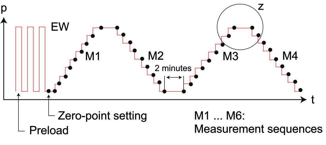
When calibrating devices of accuracy class A, the DKD stipulates three loads up to the full measurement range before the actual measurement sequences are carried out. In each instance, the maximum pressure must be maintained for 30 seconds before being fully released.

Next, nine points evenly distributed across the measurement range are to be reached by continuous pressure increase. The zero-point is deemed the first measurement point here. The target measuring points have to be reached “from below”. As a result, the pressure increase can only be performed slowly. If a target point is overshot, then the resulting hysteresis leads to a falsification of the results. In this case, the pressure must be drastically reduced in order to reach from below the measurement point to be attained. Once the value is reached, this must also be held for at least 30 seconds before it is actually read.

This process is then repeated for all remaining measurement points. But the final point holds one peculiarity, since this is held for a further two minutes and then read anew and documented.

Once completed, the second stage of the first sequence can begin. This now takes place in reverse, where the individual measurement points are reached from top to bottom. The pressure should be reduced only slowly here so that this time the target value is not undershot. This second measurement sequence ends with a reading at the zero-point.

The second measurement sequence can begin after the meter has been in a pressureless state for three minutes. The cycle of raising and lowering pressure over the individual measuring points is now repeated.

Calibration sequence A according to DKD-R 6-1 directive

In-house calibration of pressure transmitters

In most industrial applications, calibration by a specialist laboratory is not necessary and often also not practical. For the calibration of pressure gauges on-site, portable pressure calibrators would be suitable. These are not as precise as a deadweight tester, but as a rule are completely sufficient. In these hand-held devices, working standards and pressure generation are combined together. When calibrating a pressure transmitter, a zero-point calibration is carried out with the valves open, once the pressure and electrical connections between the transmitter and test instrument have been established. The individual pressure testing points can then be controlled with the integrated pump. The resulting electrical signals are measured and stored via integrated data loggers, where this data can then be read out on a PC.

How pressure transmitters also work reliably in the cold

How pressure transmitters also work reliably in the cold

Ambient temperatures have a major influence on the functionality and accuracy of pressure transmitters, with Arctic temperatures representing a particular challenge here.

In pressure measurement on a piezoresistive basis, semiconductors diffused onto a silicon membrane serve as strain gauges. When pressure acts on the membrane, these strain gauges deform and a change in resistance occurs. It is this change that ultimately gives the determined pressure. These resistors, however, are also temperature-sensitive. The sensitivity of pressure sensors is therefore decreased with sinking temperature. The pressure transducer is thus no longer as precise as at room temperature.

Because of this property, manufacturers of pressure transmitters always indicate the behavior of their products under certain temperature conditions. To achieve the most linear behavior possible, pressure transmitters are nowadays electrically compensated over a relatively wide temperature range (temperature compensation). This implies that temperature errors are automatically calculated. As a result, piezoresistive pressure transmitters can provide precise measurements over a relatively wide temperature range. Temperature effects, however, cannot be completely eliminated. For this reason, the manufacturer datasheets are generally specified with accuracy values for different temperature ranges.

Extreme cold: Pressure transmitters without O-rings

The cold not only affects the resistances in the semiconductors employed. There are four other factors that should be considered when looking for a suitable measuring instrument for outdoor applications in cold regions. Among these is the use of sealing rings. Temperatures below -20 degrees Celsius cause the sealing materials between the pressure port and the membrane to become brittle. Leakage will then render the sensor useless. No pressure transmitters with O-rings should therefore be used in regions of extreme cold. A compact pressure sensor in which the pressure port and measuring cell are directly fused together would be the right choice here.

Icing: Beware of overload pressure

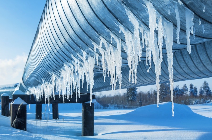
Freezing over can also affect the functionality of a sensor. If we take, for example, natural gas drilling in Arctic regions, then water can also be present in the gas-conducting pipes. When this water freezes, the pressure acting on the pressure transmitter may increase to a degree for which it has not been constructed. The consequence here can be tearing of the membrane. If there is a risk that the sensor is iced up, then a corresponding overload pressure must be watched out for.

In piezoresistive pressure measurement, the pressure is applied indirectly to the silicon membrane via a transfer medium. This usually consists of an oil. As the temperature drops, the viscosity of this oil will increase. Depending upon the oil and the actual temperature, it can gel or even harden up. This change also adversely affects the functionality of the pressure transducer.

Also to be considered is the resistance to condensation: If there is damp air in the housing of the pressure sensor, condensation will form at cold ambient temperatures, which can damage the electronics and destroy the sensor.

Summary

Users employing pressure sensors in cold temperatures should ensure that the individual components are directly fused without O-rings and are also resistant to condensation. It is also to be evaluated whether the pressure transmitter can freeze over if, for example, it comes into contact with water. In this case, a pressure transmitter with a corresponding overload pressure should be selected. As with any application, the pressure transducer should, of course, be compensated for the expected temperature range.

Grounding level sensors for protection from surges

Grounding level sensors for protection from surges

When monitoring filling levels, make sure that the level sensors are sufficiently grounded in order to prevent serious damage. Should this be inadequate or absent altogether can lead to three serious effects.

  1. Because of insufficient potential equalization in conductive media such as water, corrosion can occur. This is a gradual process, which can be observed in long-term applications. The voltage differences between the sensor and its surrounding fluid lead to electrolytic corrosion. The metal housing becomes gradually perforated and liquid then penetrates into the housing itself. Damage to the electronics will then be the consequence here. This process can be observed both in open waters and in fill level monitoring within vessels, where the potential difference between the level sensor, medium and vessel wall can cause electrochemical corrosion.
  2. Filling level sensors are connected to the control system by cables or plugged into telemetric systems. Through these connections, atmospheric voltages can be passed on to the sensor. Overstrain to the electronics will be the end result in this case.
  3. If lightning strikes near the level probe, a very high voltage difference will exist over the shorter term. The increased voltage in the water will then seek the shortest path to earth here via the level sensor.

Grounding and lightning protection of level sensors

To protect level sensors from these effects, they can be equipped with lightning protection. For this purpose, a transient overvoltage protection is integrated into the level probe, which will react to rapidly rising voltage differences. Should a sudden voltage surge occur, the lightning arrester will trigger a short circuit within the electrical circuitry to channel that overvoltage to ground. This surge protector normally operates in a non-conductive state, but does conduct voltage transients so that they can flow to ground without causing any damage. It should be noted, however, that with a direct lightning strike to the immersion probe, even overvoltage protection cannot prevent damage.

Additionally, an earth connection that should have a resistance of less than 100 ohms is used for grounding. For fill level monitoring in liquid-carrying tanks made of metal or even plastic, care must be taken that all of the isolated metallic components are connected together to ground. In open waters, a greater effort is generally required to create a low resistance to ground. For this reason, an earthing grid is often set into the ground for these applications.

Users are generally advised to discuss a grounding concept with the manufacturers in regard to their respective application.

Pressure measurement: Connections and seals

Pressure measurement: Connections and seals

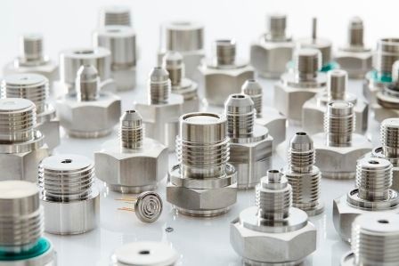
The pressure connection (also process connection) is the element via which the process medium is directed towards the pressure sensor. As with the seals, there are different variants here. As always, the requirements of the respective application determine the choice of the appropriate components.

There are a variety of pressure connections to meet the needs of different industries, as well as meet the national standards of different countries. The basic distinction, however, is between pressure connections with internal and front-flush membranes.

Pressure connections

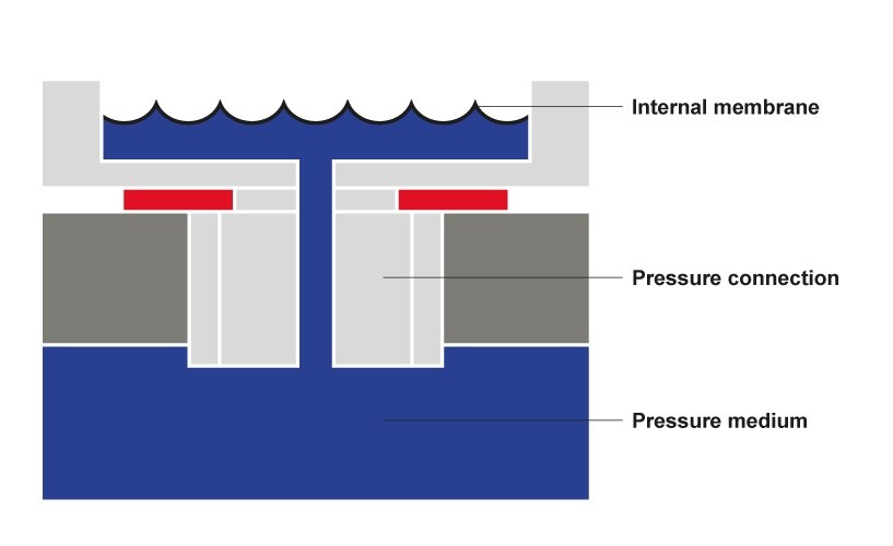
For pressure connections with an internal membrane (Figure 1), the pressure medium reaches the sensor membrane via a channel. This type of pressure connection is usually more cost-effective and is often used in applications with liquids and gases. In the case of the more solid process media, there is a risk of fouling the channel, which can ultimately lead to an influence on the measured results. Pressure connections with an internal membrane are also unsuitable for use in sterile applications.

Figure 1: Pressure connection with internal membrane

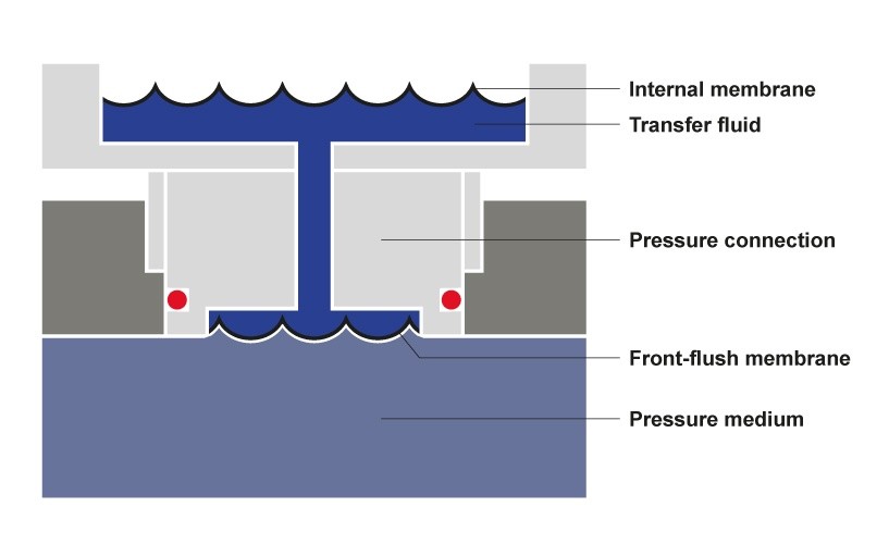
For front-flush pressure connections (Figure 2), the pressure channel is sealed from the front by a stainless steel membrane. The pressure is thus transferred indirectly to the sensitive sensor chip via a transfer fluid. This type of pressure connection is used when a residue-free cleaning is indicated (for example the CIP process). Also with viscous, solid and abrasive media, front-flush pressure connections are to be preferred.

Figure 2: Pressure connection with front-flush membrane

Screw threads and seals

The pressure connections usually have a thread with which they can be attached to the measuring point. Depending on the region, these threads may vary in form, with cylindrical pipe threads (G) being the most common in Western Europe.

The available seals, which are used between the housing and the thread, are just as varied as the thread types themselves. Here also, sector-specific and regional solutions have to be considered. In essence, it is generally the case that the materials are selected according to the existing pressure medium. In sterile applications (eg food industry), for example, O-rings made from Viton are used, since this is a fluoroelastomer exhibiting high thermal and chemical resistance. As a result, this material can also withstand the CIP and SIP processes.

Where appropriate, an application may also require the use of no sealing rings at all. Some types of threads are thus leakproof without the use of sealing rings at all. These tapered, purely metallic sealing connections achieve their sealing effect when the conical sealing surfaces of the components are wedged shut by a tightening of the threaded nut.

In the case of abrasive media or extreme cold or heat, the omission of O-rings for sealing is important. If, for example, a fuel such as diesel or gasoline is the pressure medium, then the measuring cell and the pressure connection must be welded together. The elastomers used for sealing rings would become rapidly porous under the influence of an abrasive medium. Direct welding, however, is not advisable in all situations. Here also, the medium decides upon the type of seal, since welding seams can corrode in brackish and salt water. A connection with O-rings will be required here.

Thanks to the modular construction of the pressure transmitters from STS, the pressure connections and sealing concepts can be flexibly designed and adapted to meet almost every requirement.

Subscribe To Our Newsletter

Join our mailing list to receive the latest news and updates from our team.

You have Successfully Subscribed!