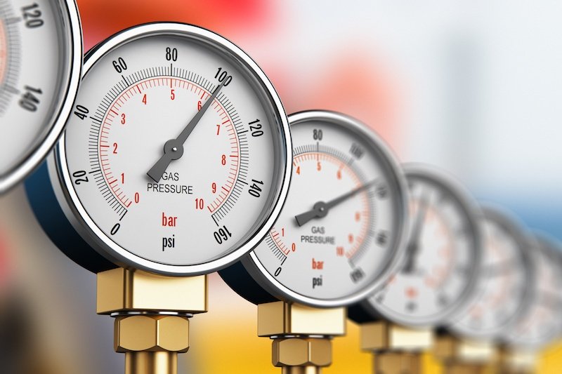
The physical values of pressure and the various forms of pressure

The physical values of pressure and the various forms of pressure

Besides temperature, pressure is one of the most frequently measured physical variables in industrial applications. There exist, however, different measurement units for, and different forms of, the pressure itself. In the following we will explain the basic prevailing terms.

Pressure describes the force (F) acting on a surface (A) and is represented by the formula symbol p:

p = F/A

According to the international system of units, the SI unit of pressure is named the Pascal (Pa). The term stems from the French mathematician Blaise Pascal (1623-1662) and is derived as follows from the SI units of meters and Newtons: 1 Pa = 1 N/m2.

The Pascal is thus a very small unit of pressure. In industrial applications, the unit of bar is therefore generally applied. The units used to indicate pressure also vary from one application area to the next. The Pa is applied for pressure measurements in clean rooms, whereas meteorology relies upon the hPa. Blood pressure, on the other hand, is measured in units of mmHg. How these individual units relate to one other is clearly shown in the conversion chart below.
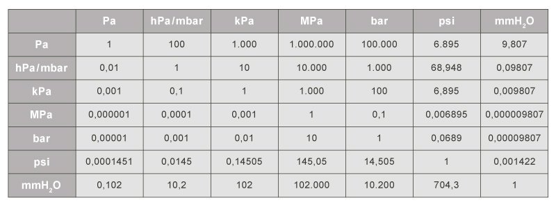
Figure 1: Pressure units conversion chart

The pressure forms

For users, it is important to be able to differentiate the different forms of pressures in order to select the ideal pressure transmitter for their application.

The subdivision into absolute, differential and relative pressure is therefore decisive to pressure measurement.

Absolute pressure

Absolute pressure is referenced to a pressure of zero. This implies an airless space, as exists, for example, in the vastness of the universe or in an ideal vacuum. The measured pressure is therefore always greater than the reference pressure. For a better differentiation from the other forms of pressure, the absolute pressure is indicated with the abs index: Pabs.

Absolute pressure sensors use a vacuum enclosed within the sensor element as a reference pressure. This is situated on the secondary side of the membrane. Besides meteorological applications, absolute pressure sensors are also often used in the packaging industry (e.g., in the manufacture of vacuum packaging).
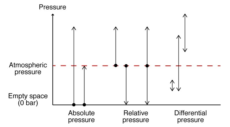
Figure 2: Summary of various pressure forms

Relative pressure (Gage pressure)

Relative pressure is referenced to the atmospheric pressure, which is indicated by the amb index. This is the pressure that acts through the earth-enveloping layer of air. This pressure decreases continuously up to an altitude of about 500 kilometers (from this elevation absolute pressure then prevails). The atmospheric pressure at sea level corresponds to about 1013 mbar and fluctuates by about five percent with high and low pressure conditions.

In contrast to an absolute pressure sensor, the secondary side of a relative pressure sensor remains open, in order to ensure pressure equalization with the atmospheric pressure. In addition to relative pressure, the term overpressure is also common. A positive overpressure is thus referred to when the absolute pressure is higher than the atmospheric pressure. When this is not the case, then a negative overpressure is expressed (previously, the term vacuum was also used).

One practical example of a relative pressure measurement is the tire pressure of a vehicle. If 2 bar of relative pressure is supplied to a tire at an air pressure of 1 bar, this would then correspond to 3 bar in absolute pressure.

Differential pressure

With differential pressure, the difference in pressure between any two pressures is indicated. For this reason, differential pressure sensors have two pressure connections.

One application example for differential pressure measurement is the hydrostatic pressure measurement within enclosed tanks. You can read more on this here.
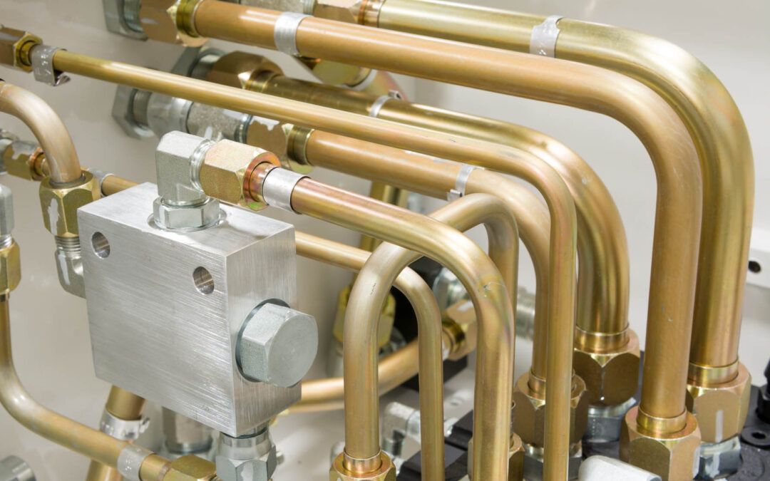
Installation of pressure sensors: The medium is decisive to positioning

Installation of pressure sensors: The medium is decisive to positioning

Ideally, pressure transmitters are installed directly within the process to be monitored. If this is not possible, the process medium to be monitored will then decide upon the positioning of those sensors.

There are various reasons why pressure transmitters cannot be mounted directly within the process:

  • there is not enough space for installation within the application
  • the pressure sensors are to be subsequently installed
  • a direct contact between process medium and measuring sensors is undesired (e.g. due to excessive temperatures)

If the pressure sensor cannot be mounted directly in the process, the connection between process and measuring instrument is established via a bypass line (also termed differential pressure line or branch line). This connecting line is filled with gas or liquid, depending on the type of application. As a rule, there will be a shut-off valve both on the bypass line near the process and also near the pressure transmitter. This allows the measuring device (or parts thereof) to be dismantled or modified without interrupting the actual process.

This is particularly helpful when the pressure transmitter is subject to maintenance work, such as calibrations.  The measured medium remains in the bypass line due to the shut-off valve on the measuring instrument.

When laying the bypass lines, a number of important points must be observed. They should be as short as possible, have rounded bends, be free of dirt and their gradients should be as steep as possible (no less than 8%). Additionally, there are also media-specific requirements. For liquids, for example, a complete venting is to be ensured. A bypass line may be used for relative and absolute pressure measurement. For differential pressure measurement, however, there will be two lines. Depending on the process, further installation instructions must also be observed here.

Positioning of pressure transmitters within the process

Depending on the type of process, it is important whether the pressure transmitter is to be mounted above or below that process.  The most important differences between liquid, gas and steam-carrying lines will now be discussed.

Fluids

When measuring fluids in pipelines, the pressure sensor should be installed below the process so that any gas bubbles can then escape back into the process.  Additionally, it must be ensured that the process medium is sufficiently cooled at high temperatures. In this case, the bypass line will also be considered a cooling section.

Gases

For gas measurements on pipelines, the pressure transmitter should, where possible, be mounted above the process. This allows any condensate that may accumulate to flow back into the process without impairing the measurements.

Steam

Steam measurements are somewhat more complex due to the high temperatures and the formation of condensate. Both of these aspects go hand in hand: If the steam cools on its way to the pressure transmitter, a condensate will form. If this should accumulate in the measuring instrument, it can then influence the measured results.

Accordingly, when measuring steam, care must be taken to ensure that the medium temperature is appropriately reduced and that the condensate produced does not enter the pressure transmitter. A height up to which condensate can collect must therefore be defined in advance. This will then be taken into account in the measurement range design. In absolute and relative pressure measurement, the bypass line is curved like an ‘S’ for this purpose.  This leads steeply upwards from the steam-carrying line before dropping downwards again. The condensate will collect in this first pipe bend and can then flow back into the process.

Things become even more complex when measuring differential pressure, since the same conditions should prevail inside both bypass lines. This means that the condensate column is the same on both the high and the low pressure sides. For this reason, condensate vessels, which are still located upstream of the extraction/shut-off valve of the bypass line, are used for steam measurement with differential pressure transmitters. The excess condensate here will then be fed back into the process via these vessels. Additionally, a five-port shut-off valve should be used on the side of the pressure transmitter so that the sensors cannot be permanently impaired by the hot medium, should the bypass line happen to blow out.

Subscribe To Our Newsletter

Join our mailing list to receive the latest news and updates from our team.

You have Successfully Subscribed!