Minimizing pollutant emissions using pressure-sensing technology

Minimizing pollutant emissions using pressure-sensing technology

Recall actions in the automobile industry have widespread consequences. Manufacturers have to contend with a huge image loss, as well as higher costs. Vehicle owners, on the other hand, react with anger and uncertainty. A particularly major stir has welled up over the past year with the scandal surrounding manipulated emissions figures. Politics has in turn reacted and signaled towards new testing procedures.

The automobile industry has triggered a true recall-crisis over the last two years. In the USA alone, some 51 million vehicles were ordered for recall during 2015 by the National Highway Traffic Safety Administration (NHTSA). This far exceeds the number actually sold in that same year, even though the vehicles recalled were not all connected to manipulated emissions figures. Some 11 million of these vehicles originate alone from the “Dieselgate” scandal involving the manufacturer Volkswagen. The losses involved are enormous.

Cost pressure and an increasing complexity of the systems built into vehicles are associated with heightened error susceptibilities and their resultant recall actions. This challenge is to be met primarily through improved and even more reliable control systems – on the part of manufacturers and suppliers, as well as government supervisory bodies responsible for legal specifications monitoring. High-grade measurement equipment is therefore needed, which can deliver the most precise of results under varying conditions and thus secure an optimal standards qualification (or post-qualification). A major backlog demand has since opened up in this respect.

The best pressure measurement technology for the best combustion engines

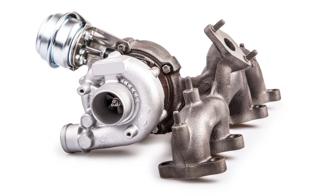
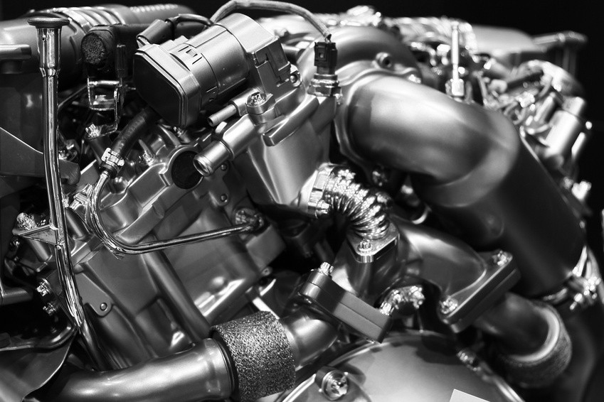
In the development of combustion engines, high-precision pressure transmitters are required, which, during combustion analysis, can facilitate the exact measurement of cylinder pressures, as well as intake and exhaust pressures. Absolute pressure sensors (gas exchange) and high-pressure sensors (injection pressure measurement) must also be of the highest-grade, since, in the latter instance especially, the potential for pollutant minimization is enormous. In this regard, particulates from gasoline engines can be reduced through an increase in injection pressure. Some suppliers are already working on increasing injection pressures to 350 bar or even higher.

Mobile emissions measurement is on the way

The standardized “New European Driving Cycle (NEDC)” is currently being introduced for exhaust and consumption measurements by state regulatory agencies. As we have witnessed, test procedures have given manufacturers all the freedom to influence measurements to their own advantage, since the vehicle is examined only in a test facility rather than under real-world conditions.

Once the manipulations became known, the Committee of Experts from the European Union decided in May 2015 that emissions during type approval are to be tested from late 2017 under practical driving conditions – known as Real Driving Emissions (RDE). The laboratory conditions for conventional checks will be supplemented by a procedure that prevents the use of cut-off devices during testing. The vehicle to be tested will be examined on an open track and thus subjected to variable conditions. Furthermore, random braking and accelerating procedures will also be performed.

Meeting new challenges – using modular pressure-sensor solutions

The RDE procedure obviously poses particular challenges to the measurement technology deployed. In the optimization of emissions figures for combustion engines, initial emphasis falls upon absolute and relative pressure measurement. With the new measurement procedures in mind, these need to perform reliably across a broad temperature range. Whether in the depths of winter or the heights of summer, measured values must be absolutely reliable to reflect a realistic picture of the true exhaust figures. It is also evident that operation at higher pressures can achieve significant reductions. For this reason, higher pressures must also be measurable. The fact that the pressure sensing technology employed operates without failure in mobile applications, given the new procedures, goes largely without saying.

Standard solutions cannot achieve this objective. Even more than that, they are actually part of the problem. Individual challenges require individual solutions. Also required are instruments that are precise as well as flexible enough to perform reliably in differing applications. Only by following this path can cost-efficiency and precisions be reconciled. It is clear that modular systems would be ideal in this context. In coordination with the manufacturer, these can be adapted to individual requirements and thus deliver highly reliable results. This represents a particular advantage in the development of new engines, since the adaptations can be made both straightforwardly and also promptly.

An experience that our customers have been making daily – and for almost 30 years now. As a leading manufacturer of customer-specific, modular measurement systems, we can provide tailored pressure measuring solutions within a short timeframe and in a proficient cooperation with manufacturers. Viewed from a measurements perspective, there exist no obstacles to the development of new, fuel-efficient engines, as well as to their testing under real-world practical conditions.

Mapping boost pressure on downsized turbo engines is the key to success

Mapping boost pressure on downsized turbo engines is the key to success

To meet ever tightening emissions legislation across the world OEMs are turning to downsized Spark Ignition engines. While these smaller engines consume less fuel and produce significantly lower emissions they require forced induction to deliver the performance drivers have come to expect from modern passenger vehicles.

The driveability of these downsized turbo engines must at least equal the performance of their naturally aspirated equivalents. This requires full boost pressure at low engine speeds without running out of steam at high speed, which can only be achieved with a sophisticated boost pressure control system.

The main problem with these forced induction spark ignition engines is the precise control of the air-fuel ratio near stoichiometric values at different boost pressures. At low speeds, these engines are prone to knock under medium to high loads.

Modern pressure control systems

Controlling the turbine-side bypass is the simplest form of boost pressure control.

Once a specific boost pressure is achieved, part of the exhaust gas flow is redirected around the turbine via a bypass. A spring-loaded diaphragm usually operates the wastegate which opens or closes the bypass in response to the boost pressure.

In recent times manufacturers have turned to variable turbine geometry to regulate boost pressure. This variable geometry allows the turbine flow cross-section to be varied to match the engine operating parameters.

At low engine speeds, the flow cross-section is reduced by closing the guide vanes. The boost pressure and hence the engine torque increases as a result of the higher pressure drop between turbine inlet and outlet. During acceleration from low speeds the vanes open and adapt to the corresponding engine requirements.

By regulating the turbine flow cross-section for each operating point the exhaust gas energy can be optimised, and as a result the efficiency of the turbocharger and therefore that of the engine is higher than that achieved with bypass control.

Today, electronic boost pressure regulation systems are increasingly used in modern Spark Ignition petrol engines. When compared with purely pneumatic control, which can only function as a full-load pressure limiter, a flexible boost pressure control allows an optimal part-load boost pressure setting.

The operation of the flap, or vanes, is subjected to a modulated control pressure instead of full boost pressure, using various parameters such as charge temperature, ignition timing advance and fuel quality.

Simulation reduces time to production and development costs

Faced with a plethora of complex variables, manufacturers have turned to simulation during the design and test phase.

A significant hurdle to overcome with downsized turbocharged engines is the narrow range within which the centrifugal compressor operates stably at high boost pressures.

The only way to build an effective simulation model is through extensive real world testing. This testing is mostly carried out on engine dynamometers in climatic chambers.

During wide open, and part throttle, runs the following pressure information is recorded:

  • Intake manifold pressure
  • Boost pressure
  • Barometric pressure

Of course this is all integrated with engine temperatures (Coolant and oil) to gain a picture of engine performance over the full engine speed range.

During this testing it’s important that engineers note any abnormalities in performance, as events such as exhaust pulses at specific engine speed can set up standing waves which can excite the impeller at a critical frequency which will reduce the life of the turbo, or even lead to catastrophic failure.

Therefore the measurement of pressure performance maps of both compressor and turbine is vital for the creation of an accurate extrapolation model for implementation during simulation.

A well-developed simulation tool can save the OEM time and money in dynamometer and road tests, but can only be developed once the pressure maps have been completed.

Pressure sensors in motorsport: Where a fraction of a horsepower is decisive

Pressure sensors in motorsport: Where a fraction of a horsepower is decisive

“The winner takes it all!” The world of motor racing is divided into winners and losers, with the successful driver enjoying the champagne shower. The preliminary outcome, however, takes place on the engine development test bed, with high-performance pressure sensors representing the decisive competitive advantage.

STS supplies pressure sensors to customers from the world of motorsport, including participants in Formula 1 and NASCAR. Both of these racing series, despite all their differences, have one thing in common. Every horsepower counts and embodies the decisive advantage on the track. When every tenth of a horsepower is to be wrestled from extensive analysis on engine testbeds, the end results have to be absolutely reliable down to last decimal place.

Pressure measurement technology in Formula 1 engine development

The current engine regulations in Formula 1 were introduced in 2014. V-layout engines of six cylinders, 1.6 liters displacement and a single turbocharger are driven. The rev speeds reach up to 15,000 min−1. The Kinetic Energy Recovery System (KERS), an electrical system for recovering energy under braking first introduced in 2009, has now been replaced by the Energy Recovery System (ERS). In modern Formula 1, the engines involved are thus of a hybrid type. The future of Formula 1, for this reason, has long since become the present. The perhaps most successful racing series worldwide is also a testing laboratory for the road. From disc brakes to computer diagnostics, many technologies now found in everyday road traffic have their origins in the development centers of Formula 1.

The prevailing engine regulations, which evenly delineate the parameters for all teams, make thorough research on the testbed essential to carving out the decisive advantage. Every single horsepower counts. In comparison to tests for vehicles in normal road traffic, different requirements, to some extent, are applied. Oil and water pressures are higher, as are their arising temperatures. When improved fuel economy and increased performance is the aim, then extensive testing under racing conditions is essential. Furthermore, the precision of measured results across the required temperature range is of great significance. In Formula 1, major leaps in terms of horsepower are often not the case – improvements even in the decimal regions are a reason for celebration at this elevated performance level.

In light of these challenges, a well known racing team from Formula 1 approached STS, since the hitherto employed sensor technology failed to meet their high requirements. The measuring instruments used were too big and too heavy. Even more serious, however, was the problem that additional cooling technology had to be built into the testbed, since the sensor temperatures would otherwise rapidly escalate above the maximum. Measured results under this scenario would thus be worthless.

The aim of the developers was to acquire pressure sensors that permit standardization and make additional cooling elements obsolete. The topics of weight and size also play a role, since these factors influence the performance of the speeding car.

STS provided the racing team with a new sensor from the ATM series, available on the market from the fall of this year. This sensor scored not only in its desired precision across the required temperature range, but also delivered a further decisive advantage which could enduringly optimize engine development. With the previously used sensors from another manufacturer, there were malfunctions when switching to the hybrid systems employed since 2014. The results were that the testbed would shut itself down and longer term measurements were practically impossible. The ATM sensors from STS are fail-safe and thus allow for extensive testing on the road to the victory podium.

Pressure measurement technology in NASCAR engine development

Although hybrid engines are not built into NASCAR stock cars, extensive testing is still required to attain the optimum in performance. In this sport also, a well known engine manufacturer has opted for the pressure measurement technology from STS. During extensive tests, some 200 ATM.1ST pressure transmitters have been keeping an eye on oil, water, fuel and air pressures. From air pressures reaching the engine right through to improvements in oil flow, the aim is to precisely examine various factors to attain even the slightest increase in performance (involved here is ca. 900 PS). As with Formula 1, the highest of precision is required. The scope here amounts to just a tenth of a horsepower!

The manufacturer choice went to the ATM.1ST pressure transmitter, since it is largely unrivalled in its required performance characteristics.

  • The modularity of STS sensors also allows the manufacturer to connect a special pressure adapter.
  • A total error of ≤ ± 0.30 % FS permits meaningful analyses for improving engine performance.
  • Long-term stability considerably minimizes the need for calibration.
  • The pressure measuring range from 100 mbar…1,000 bar is well suited to those pressures arising during engine development.
  • Outstanding temperature compensation allows for precise results across a broad temperature range – a decisive criteria for the sharply rising temperatures during performance testing at these highest levels.

Whether in Formula 1 or NASCAR, the path to the victory podium leads through engine testbeds. In the high-performance motorsport field in particular, high-precision sensors are required for monitoring all of the important data from oil and water pressures to fuel and air pressures. Besides precision, fail-safe capability also plays an important role in being able to conduct essential long-term testing that yields reliable results.

GDI engines come under pressure to reduce particulate emissions and improve performance

GDI engines come under pressure to reduce particulate emissions and improve performance

With some 40 million gasoline direct-injection (GDI) engines expected to be sold by 2025, it may be surprising to learn that these units emit more hazardous fine particulate matter than a port fuel-injected engine (PFI), or even the latest heavy-duty diesels equipped with a particulate filter.

The potential increase in the market means that GDI particulate emissions, though low compared to those of an unfiltered diesel, are now coming under scrutiny from regulators and manufacturers alike.

To reduce these emissions and improve overall performance engineers are studying new combustion designs and engineering concepts, including increasing the fuel pressure, alternate fuels and exhaust emissions control.

According to Matti Maricq, technical leader in chemical engineering and emissions after treatment at Ford’s Research and Innovation Center in Dearborn, injecting fuel directly into the cylinder enables a clean-burning explosion that wastes little fuel and delivers greater power.

During this process gasoline is sprayed directly where the combustion chamber is the hottest (rather than in the air intake), allowing for a more thorough, even and leaner burn.

Cleaner burning GDIs emit harmful particulates.

But because of incomplete fuel volatilization, partially fuel-rich zones and the “wetting” of piston and cylinder surfaces, GDI engines produce unwanted particulate matter. Most emissions typically occur during cold start and high load transient conditions during the warm-up phase, but this can vary according to load, drive-cycle phase and driver demands.

While “green” critics remain sceptical about so-called “engine management” methods, believing them to be unreliable compared to exhaust filters, most OEMs and component suppliers expect that combustion design and engineering changes will prove more cost-efficient and eventually equally effective.

Current development indicates that higher fuel pressure, possibly touching on 40MPa,together with new ultra-precision injectors will greatly improve future GDI systems. To further optimise the system engineers will also continue to improve injector timing, targeting, metering and atomization.

In a recent study, published by the SAE, it was established that an increase in fuel system pressure improved the homogeneity of the mixture and reduced the tip diffusion flame thereby significantly reducing particulate emissions under homogenous combustion in a GDi engine.

Furthermore, as a result of the enhanced intake charge motion at fuel pressures of between 20 MPa to 40 MPa a further reduction of particulate emissions was achieved.

As indicated by the combustion data, an increase in fuel pressure has a significant impact on the reduction of combustion emissions as well as improving fuel consumption.

However for a GDi system to operate optimally it’s important that, during the design and testing phase the pressure of the fuel in the common rail (CR) is correctly measured so that the ECU can be mapped accordingly.

Measurement of CR fuel pressure is key to lower particulate emissions.

Direct injection pressure is measured with sensors, and the signals are used to determine pump speed and/or volume.

Most direct injection systems use piezo-resistive pressure sensors on the low side of the system. The silicone chip element generates a measurable electrical voltage when pressure is applied, increasing as pressure increases.

On the high-pressure side sensors usually use a metallic membrane on a resistance bridge. When pressure is applied, the bridge generates a change in resistance that results in a change in the applied voltage. The Electronic Control Module (ECM) transforms the voltage into a calculated pressure, generally to within a ±2% accuracy.

To maintain the correct pressure, the ECM pulses the low-pressure pump. The system typically has a regulator and no return lines. Some systems even have integrated temperature sensors in the lines that are used to calculate the density of the fuel so that the fuel trim can be tuned to the amount of energy in the fuel.

To ensure accurate measurement of the line pressure it’s important that high precision pressure transmitters are used to map the pressure within the CR under all engine and load conditions. Any errors in this process can result in incorrect modulation of CR pressure which in turn can result in serious abnormalities, such as cylinder wash which can occur if the CR mean pressure exceeds the injector design pressure when fuel delivery is increased at high loads.

Additionally, with the introduction of the harmonized driving cycle OEMs will be under renewed pressure to meet emissions targets set by regulators, and GDI spark ignition engines will be at the forefront of a new generation of green technologies. However, for this technology to meet upcoming legislation particulate emissions need to be reduced, largely through the accurate control of the CR fuel pressure.

It’s time to rethink engine cooling

It’s time to rethink engine cooling

All internal combustion engines experience significant energy “loss” due to the inefficient conversion of chemical energy into heat and subsequently, kinetic energy. Even a modern F1 engine is relatively wasteful when it comes to converting the power available from the fuel/air mixture into power at the rear wheels. This is measured in terms of ‘thermal efficiency,’ and is typically in the region of 30%: that’s to say, if a typical F1 engine produces slightly under 650 KW on the dyno, something like another 1500 KW does no work in propelling the car.

So where does it go? A small percentage is turned into the distinctive sound of an F1 car. The vast majority, though, must be dissipated as heat from a number of areas: for example, the oil dispels around 120 KW and the water system 160 KW. The inefficiencies of the gearbox will mean it has to dissipate around 15 KW, while the hydraulics represent a further 3 KW.

In these high-performance engines, the coolant systems are commonly pressurized up to 3.75 bar and have a boiling point around 120°C.

In the modern passenger car, coolant system pressures are characteristically in the order of between 0.9 to 1.1 bar, raising the boiling point by about 22°C  resulting in an engine coolant operating temperature of about 100°C.

At the same time, a typical water pump can move a maximum of about 28,000 liters of coolant per hour, or recirculate the coolant in the engine over 20 times per minute, whilst drawing off up to 2 KW in parasitic losses.

These figures are well known and have been used as a rule of thumb by automotive engineers for over 100 years: But downsizing to meet ever tightening emissions requirements, and the proliferation of hybrid electric vehicles are changing the rules.

Going electric saves power, but beware the pressure

Manufacturers are studying, in depth, all parasitic losses in an endeavor to increase the efficiency of current and future powertrains. This includes a relook at the coolant system, and in particular the mechanical water pump.

Whilst the decoupling of the water pump from the engine achieves significant savings, it basically requires a requalification of the entire cooling system’s performance; including the operating pressures under varying temperatures, and engine speeds.

With the delivery of the electric motor no longer directly proportional to the engine speed, but rather dependent on the engine’s requirement it’s important that, during development, the cooling system pressure be monitored at all times. This ensures that components such as the radiator and water hoses remain in the safe operating zones.

During the development of what is principally a new technology, mapping the system’s pressure requires highly responsive pressure sensors of unquestionable quality and accuracy. There are a handful of specialist pressure transmitter manufacturers that meet all these requirements.

While these sensors have to accurately record data, they also need to be robust: The operating environment demands that they function faultlessly over a wide temperature range, and withstand vibration and exposure to chemicals.

Although currently mostly fitted to high-end models such as BMW and Mercedes Benz, this technology will rollout to other segments as new models come to market. And all of these will have undergone the same stringent cooling system qualification to ensure durability and safeguard the very costly engine.

Subscribe To Our Newsletter

Join our mailing list to receive the latest news and updates from our team.

You have Successfully Subscribed!