Deprecated: Hook wp_smush_should_skip_parse is deprecated since version 3.16.1! Use wp_smush_should_skip_lazy_load instead. in /home/xepoxenu/www/new.stssensors.com/wp-includes/functions.php on line 6078
Electronic Pressure Measurement Archives - STS Switzerland (EN)
Deprecated: Hook wp_smush_should_skip_parse is deprecated since version 3.16.1! Use wp_smush_should_skip_lazy_load instead. in /home/xepoxenu/www/new.stssensors.com/wp-includes/functions.php on line 6078
Miniaturization, increased efficiency, reduced consumption: Mobile air conditioning using carbon dioxide

Miniaturization, increased efficiency, reduced consumption: Mobile air conditioning using carbon dioxide

Carbon dioxide has been recognized as a refrigerant for over 150 years now. The fact that it is only now gaining entry into mobile air conditioning is due to lawmaker-applied pressure for reducing greenhouse gases and also to improved technical capabilities. Pressure measurement plays a central role in this latter process.

Fluorinated greenhouse gases with a Global Warming Potential above 150 have been forbidden by an EU directive since January 2011 in vehicle air conditioning. In the meantime, the common tetrafluoroethane refrigerant (R134a) has thus had to be used in substitution. Because CO2 is 1,430 times less harmful to the climate than R134a, it offers itself as an alternative due to its increased cooling performance and good chemical characteristics.

The arguments for CO2 as a refrigerant can no longer be dismissed.

  • As a naturally occurring gas, it enjoys both unlimited worldwide availability and cost-effectiveness.
  • It is far less damaging than other coolants, such as R134a, R404A, R407C and others.
  • Being a by-product of industrial processes, it has no need for expensive manufacture.
  • In contrast to other new refrigerants, it has already been well researched toxicologically.
  • It is neither toxic nor inflammable and thus represents a lower hazard risk than other materials.
  • It is also compatible with all other common materials.
  • It displays a very high cooling performance volumetrically and is also suited to heat pumps.

The switch from R134a to R744 (the abbreviation for CO2 in refrigerant form), however, cannot be simply implemented as is. Certain disadvantages stand in the way of its manifold virtues, which incidentally only apply in the case of constructing mobile air conditioners for vehicle use. A very high working pressure and its low critical temperature of 31°C are to be highlighted here. The conversion to R744 must therefore make a necessary detour via manufacturer test beds and those of their suppliers.

Air conditioning with CO2 – How it works

The operation of a common air conditioner begins, of course, with activation of an AC switch inside the vehicle. As a result, the magnetic coupling on the compressor is energized (although newer compressors have no magnetic coupling, with pressure being regulated internally by the piston stroke). A linkage between the pulley and compressor shaft is then established, with the compressor now drawing in the gaseous refrigerant. It now becomes condensed here and then forced into the high-pressure piping. In this process, however, the coolant temperature rises. The condenser built into the front end of the vehicle is responsible for lowering this temperature again. At this stage, the physical state of the refrigerant shifts from gaseous to liquid. The now fluid coolant is diverted to the receiver-dryer, where any moisture is removed. Next, the coolant is passed through the expansion valve. After passing this constriction, the refrigerant again alters its physical state inside the following evaporator. The energy required for this change is drawn from the ambient air, which in turn lowers the temperature within the vehicle interior. The gaseous coolant can now be drawn in again by the compressor, allowing the cycle to begin anew.

This cooling principle also remains the same for R744 application. The only difference is that the technical framework becomes somewhat altered. Because of its characteristics, carbon dioxide places other requirements upon the system in regard to pressure and temperature.

In comparison to a common mobile cooling system, the additional inner heat exchanger represents the biggest difference of all. This is essential because air conditioners using CO2 function with supercritical heat dissipation above 31°C. The cooling cycle proceeds as follows: The gas is condensed to a supercritical pressure inside the compressor. From there it enters a gas cooler, which performs the role of the condenser, when compared to common systems. The gas is cooled here, but no condensation takes place. A further cooling then occurs in the following heat exchanger. In the next step, the CO2 is pushed through the expansion valve, transforming the gas into a vapor form. This vapor portion is next evaporated within the evaporator, where the cooling-effect then takes place.

Apart from the inner heat exchanger and the gas cooler replacing the condenser, the high pressure essential to this system represents the biggest difference to previous mobile cooling systems. The demands upon the sturdiness of all components utilized increases in line with system pressure. This high pressure particularly influences compressor construction, which needs to be freshly designed as a result.

High pressures require high-performance measurement technology

A central aspect in the construction of new compressors is depicted by the very small molecular size of CO2, since it quickly diffuses through common sealing materials. An entirely freshly conceived shaft seal is thus required to prevent loss of cooling. This seal has to stand up to the refrigerant’s chemical characteristics and be able to withstand high compressor pressures in continuous operation – which can be determined during long-term testing on a test bed.

Even the compressor housing itself cannot be simply adopted from common cooling systems. To operate efficiently over the longer term, it must be able to withstand high temperatures. Heavily fluctuating suction pressures, which decisively influence drive chamber pressures, also represent a significant challenge. On the high-pressure side, maximal values can potentially attain a level of 200 bar. Because of these characteristics, leakages would occur much faster among common compressors than when operating using R134a. Compared to several years ago, a much more precise production of these components is possible today and this problem can now be overcome. A constant monitoring of pressures during prototype construction is therefore imperative.

The high pressures arising from climate systems using CO2 has further advantages beyond good environmental attributes and better cooling performance compared to R134a. Because of the higher density of CO2, the installation space needed is reduced in comparison to similar or even better-performing coolers using R134a. For the same cooling performance, only 13% of the volumetric flow of an R134a refrigerant compressor is required.

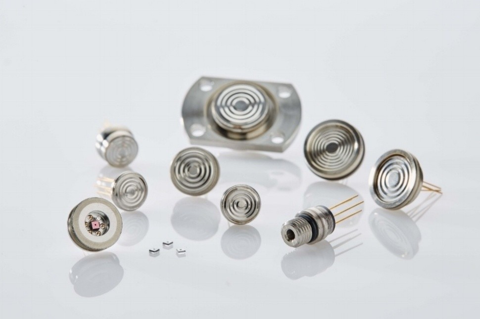
This reduction in size also reinforces the case for increasingly compact pressure measurement technology. Pressure sensors of a piezoresistive type offer themselves here due to their miniaturization capabilities, highly precise function at low pressures and even their exact results in the higher pressure ranges – in particular during long-term testing. The piezoresistive type of pressure transmitters from STS additionally offer manufacturers developing new models the decisive advantage that these instruments, thanks to their modular construction, can be quickly adapted to new requirements.
It’s time to rethink engine cooling

It’s time to rethink engine cooling

All internal combustion engines experience significant energy “loss” due to the inefficient conversion of chemical energy into heat and subsequently, kinetic energy. Even a modern F1 engine is relatively wasteful when it comes to converting the power available from the fuel/air mixture into power at the rear wheels. This is measured in terms of ‘thermal efficiency,’ and is typically in the region of 30%: that’s to say, if a typical F1 engine produces slightly under 650 KW on the dyno, something like another 1500 KW does no work in propelling the car.

So where does it go? A small percentage is turned into the distinctive sound of an F1 car. The vast majority, though, must be dissipated as heat from a number of areas: for example, the oil dispels around 120 KW and the water system 160 KW. The inefficiencies of the gearbox will mean it has to dissipate around 15 KW, while the hydraulics represent a further 3 KW.

In these high-performance engines, the coolant systems are commonly pressurized up to 3.75 bar and have a boiling point around 120°C.

In the modern passenger car, coolant system pressures are characteristically in the order of between 0.9 to 1.1 bar, raising the boiling point by about 22°C  resulting in an engine coolant operating temperature of about 100°C.

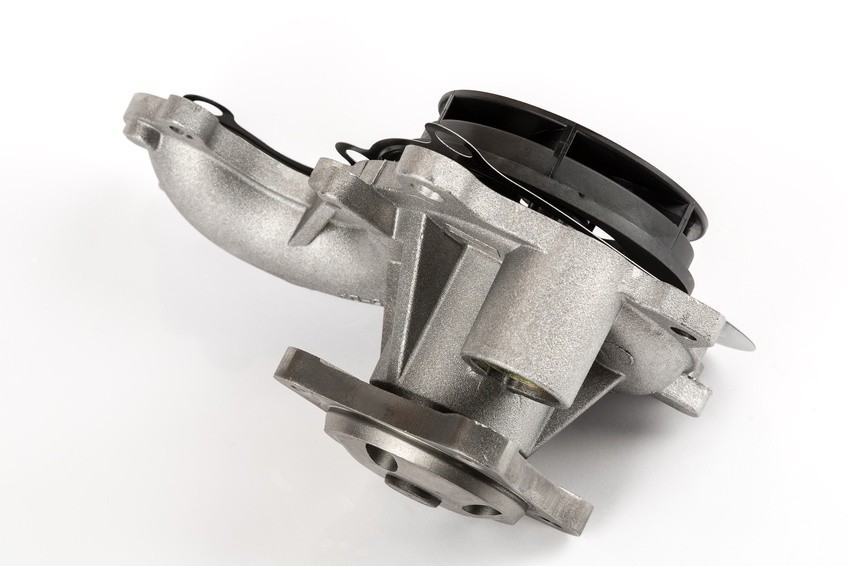
At the same time, a typical water pump can move a maximum of about 28,000 liters of coolant per hour, or recirculate the coolant in the engine over 20 times per minute, whilst drawing off up to 2 KW in parasitic losses.

These figures are well known and have been used as a rule of thumb by automotive engineers for over 100 years: But downsizing to meet ever tightening emissions requirements, and the proliferation of hybrid electric vehicles are changing the rules.

Going electric saves power, but beware the pressure

Manufacturers are studying, in depth, all parasitic losses in an endeavor to increase the efficiency of current and future powertrains. This includes a relook at the coolant system, and in particular the mechanical water pump.

Whilst the decoupling of the water pump from the engine achieves significant savings, it basically requires a requalification of the entire cooling system’s performance; including the operating pressures under varying temperatures, and engine speeds.

With the delivery of the electric motor no longer directly proportional to the engine speed, but rather dependent on the engine’s requirement it’s important that, during development, the cooling system pressure be monitored at all times. This ensures that components such as the radiator and water hoses remain in the safe operating zones.

During the development of what is principally a new technology, mapping the system’s pressure requires highly responsive pressure sensors of unquestionable quality and accuracy. There are a handful of specialist pressure transmitter manufacturers that meet all these requirements.

While these sensors have to accurately record data, they also need to be robust: The operating environment demands that they function faultlessly over a wide temperature range, and withstand vibration and exposure to chemicals.

Although currently mostly fitted to high-end models such as BMW and Mercedes Benz, this technology will rollout to other segments as new models come to market. And all of these will have undergone the same stringent cooling system qualification to ensure durability and safeguard the very costly engine.

Basics of flow measurement

Basics of flow measurement

The flow of a gas or liquid is measured for a variety of reasons, certainly including commercial considerations as part of a contract and also in various production processes. The flow or volume flow (volume/time) can be recorded, among other things, by the measured value of pressure.

Volume flow can be measured using various methods. In addition to ultrasonic flow sensors, these include magnetic-inductive flow sensors and sensors that work according to the differential pressure method, among these being the orifice plate, Venturi nozzle and the Prandtl pitot tube. When evaluating the measured values, the Bernoulli equation is used for all sensors operating on the differential pressure method:

Q = V/t = VmA

Q = volume flow
Vm = median velocity
t = time
A = area
V = volume

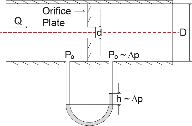
We will now take the measurement of volume flow using an orifice plate as the example. By attaching the plate to a pipe, this then becomes narrowed at one point.

Image 1: Orifice plate

With a smooth flow, the same pressure should prevail both before and after the orifice plate:

p1 + ½ ρv12=p2+ ½ ρv22

p = pressure
ρ = density
v = velocity

This assumption is based on the continuity equation, which states that everything flowing into a pipe eventually also comes out:

v1A1 = v2A2

v = velocity

A = area

Image 2: Flow measurment

Under realistic conditions, however, friction occurs, which then leads to a pressure drop:

p + ½ ρv2 + wR = constant

p = pressure
ρ = density
v = velocity
wR = rate of frictional force by volume

Image 3: Pressure drop 

This pressure drop is important in determining the volume flow. The friction effect itself, however, depends upon many factors. For this reason, an empirical formula is used, which in turn relies on empirical values. The volume flow now ultimately results from the root of the pressure differential:

Q = 4000 αεd2√∆p/ρ

Q = volume flow
α = empirical flow coefficient
ε = expansion factor
d = internal orifice diameter
∆p = pressure differential
ρ = density

To make this formula a little easier for users, all of the constant values from the measuring system and the measuring medium can be summed up as the constant ‘c’. The result for a fluid, for example, then offers the equation:

Q = c √∆p

Electronic pressure measurement: Comparison of common measuring principles

Electronic pressure measurement: Comparison of common measuring principles

Electronic pressure transmitters are used in a variety of applications, from machine technology to the manufacturing sector right through to the foodstuffs and pharmaceuticals industries. The recording of the physical size of pressure can take place via different measuring principles. We introduce the common technologies here.

In electronic pressure measurement, a distinction is usually made between thin-film sensors, thick-film sensors and piezoresistive pressure sensors. It is common to all three measurement principles that the physical quantity of pressure is converted into a measurable electrical signal. Equally fundamental to all three principles is a Wheatstone bridge: a measurement device for the detection of electrical resistances, which itself consists of four interconnected resistors.

Piezoresistive pressure sensors: High-precision and cost-effective

Piezoresistive pressure sensors are based on semiconductor strain gauges made of silicon. Four resistors connected to a Wheatstone bridge are diffused onto a silicon chip. Under pressure, this silicon chip will deform and this deformation then alters the conductivity of the diffused resistors. The pressure can then ultimately be read from this shift in resistance.

Because the piezoresistive sensor element is very sensitive, it must be shielded from the influence of the measuring medium. The sensor is therefore located inside a diaphragm seal, with pressure being transmitted via a liquid surrounding the sensor element. The usual choice here is silicone oil. In hygienic applications such as in the foodstuffs or pharmaceuticals industries, however, other transfer fluids are also used. A dry measuring cell from which no liquid will escape in the event of damage is not possible.

The advantages:

  • very high sensitivity, pressures in the mbar range measurable
  • high measuring range possible, from mbar to 2,000 bar
  • very high overload safety
  • excellent accuracy of up to 0.05 percent of span
  • small sensor design
  • very good hysteresis behavior and good repeatability
  • basic technology comparatively inexpensive
  • static and dynamic pressures

The disadvantages:

Thin-film sensors: Long-term stability but expensive

In contrast to piezoresistive pressure sensors, thin-film sensors are based on a metallic main body. Upon this, the four resistors connected to a Wheatstone bridge are deposited by a so-called sputtering process. The pressure is thus detected here also by a change in resistance caused by deformation. Besides the strain gauges, temperature compensation resistors can also be inserted. A transfer liquid, as in the case of piezoresistive pressure sensors, is not necessary.

The advantages:

  • very small size
  • pressures up to 8,000 bar measurable
  • outstanding long-term stability
  • no temperature compensation required
  • high accuracy
  • high burst pressure
  • static and dynamic pressures

The disadvantages:

  • lower sensitivity than piezoresistive sensors, so low pressures are less measurable
  • basic technology comparatively expensive

Thick-film sensors: Particularly corrosion-resistant

Ceramics (alumina ceramics) serve as the basic material for thick-film sensors. These pressure sensors are monolithic, meaning that the sensor body consists of only one material, which ensures an excellent long-term stability. Furthermore, ceramics are particularly corrosion-resistant against aggressive media. With this type of sensor, the Wheatstone bridge is printed onto the main body by means of thick-film technology and then baked on at high temperature.

The advantages:

  • very good corrosion resistance
  • no temperature compensation required
  • good long-term stability
  • no diaphragm seal needed

The disadvantages:

  • not suitable for measuring dynamic pressures
  • limited upper pressure range (about 400 bar)
Installation of pressure sensors: The medium is decisive to positioning

Installation of pressure sensors: The medium is decisive to positioning

Ideally, pressure transmitters are installed directly within the process to be monitored. If this is not possible, the process medium to be monitored will then decide upon the positioning of those sensors.

There are various reasons why pressure transmitters cannot be mounted directly within the process:

  • there is not enough space for installation within the application
  • the pressure sensors are to be subsequently installed
  • a direct contact between process medium and measuring sensors is undesired (e.g. due to excessive temperatures)

If the pressure sensor cannot be mounted directly in the process, the connection between process and measuring instrument is established via a bypass line (also termed differential pressure line or branch line). This connecting line is filled with gas or liquid, depending on the type of application. As a rule, there will be a shut-off valve both on the bypass line near the process and also near the pressure transmitter. This allows the measuring device (or parts thereof) to be dismantled or modified without interrupting the actual process.

This is particularly helpful when the pressure transmitter is subject to maintenance work, such as calibrations.  The measured medium remains in the bypass line due to the shut-off valve on the measuring instrument.

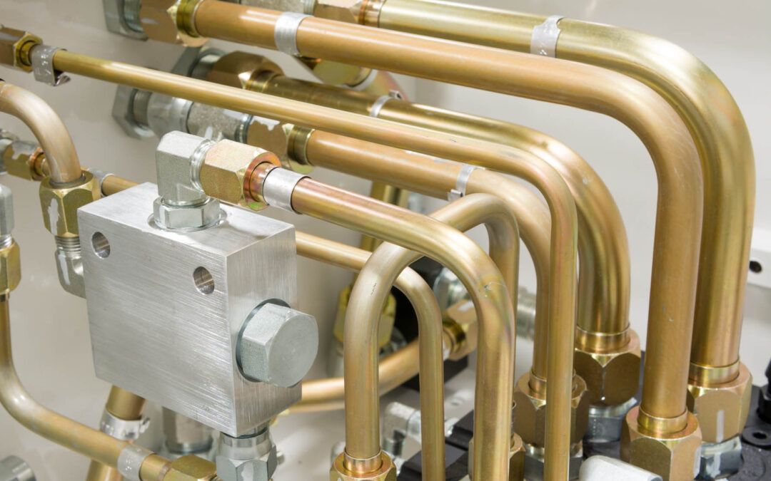
When laying the bypass lines, a number of important points must be observed. They should be as short as possible, have rounded bends, be free of dirt and their gradients should be as steep as possible (no less than 8%). Additionally, there are also media-specific requirements. For liquids, for example, a complete venting is to be ensured. A bypass line may be used for relative and absolute pressure measurement. For differential pressure measurement, however, there will be two lines. Depending on the process, further installation instructions must also be observed here.

Positioning of pressure transmitters within the process

Depending on the type of process, it is important whether the pressure transmitter is to be mounted above or below that process.  The most important differences between liquid, gas and steam-carrying lines will now be discussed.

Fluids

When measuring fluids in pipelines, the pressure sensor should be installed below the process so that any gas bubbles can then escape back into the process.  Additionally, it must be ensured that the process medium is sufficiently cooled at high temperatures. In this case, the bypass line will also be considered a cooling section.

Gases

For gas measurements on pipelines, the pressure transmitter should, where possible, be mounted above the process. This allows any condensate that may accumulate to flow back into the process without impairing the measurements.

Steam

Steam measurements are somewhat more complex due to the high temperatures and the formation of condensate. Both of these aspects go hand in hand: If the steam cools on its way to the pressure transmitter, a condensate will form. If this should accumulate in the measuring instrument, it can then influence the measured results.

Accordingly, when measuring steam, care must be taken to ensure that the medium temperature is appropriately reduced and that the condensate produced does not enter the pressure transmitter. A height up to which condensate can collect must therefore be defined in advance. This will then be taken into account in the measurement range design. In absolute and relative pressure measurement, the bypass line is curved like an ‘S’ for this purpose.  This leads steeply upwards from the steam-carrying line before dropping downwards again. The condensate will collect in this first pipe bend and can then flow back into the process.

Things become even more complex when measuring differential pressure, since the same conditions should prevail inside both bypass lines. This means that the condensate column is the same on both the high and the low pressure sides. For this reason, condensate vessels, which are still located upstream of the extraction/shut-off valve of the bypass line, are used for steam measurement with differential pressure transmitters. The excess condensate here will then be fed back into the process via these vessels. Additionally, a five-port shut-off valve should be used on the side of the pressure transmitter so that the sensors cannot be permanently impaired by the hot medium, should the bypass line happen to blow out.

Subscribe To Our Newsletter

Join our mailing list to receive the latest news and updates from our team.

You have Successfully Subscribed!