Deprecated: Hook wp_smush_should_skip_parse is deprecated since version 3.16.1! Use wp_smush_should_skip_lazy_load instead. in /home/xepoxenu/www/new.stssensors.com/wp-includes/functions.php on line 6078
Oil Pressure Archives - STS Switzerland (EN)
Deprecated: Hook wp_smush_should_skip_parse is deprecated since version 3.16.1! Use wp_smush_should_skip_lazy_load instead. in /home/xepoxenu/www/new.stssensors.com/wp-includes/functions.php on line 6078
Test fixture pressure sensors – Pressure measurement in the aircraft engine compartment

Test fixture pressure sensors – Pressure measurement in the aircraft engine compartment

As many engineers have found to their chagrin, dealing with pressure measurements in the engine compartment of an aircraft can be a delicate and frustrating experience. The heat, vibrations, orientation, and a multitude of other factors come into play. So how can we hope to develop a method for consistent and accurate readings? Well naturally, we’re left with hours, days, and most likely months of testing! However, we still need a test sensor that can rise to the occasion, function through all these changing conditions, and continually produce correct and repeatable results. We are engineers after all, and repeatable results are an occupational necessity. Thankfully for us, STS has stepped up to the plate to provide a complete series of pressure sensors to meet all of our testing needs. Where those needs can range from specific temperature requirements, size constraints, sealing material, and electrical output signals. All of these requirements will be covered in the following article as we address STS pressure transmitter usage for our testing needs.

Continuing with our engine compartment example, let’s zero in on the oil pressure. One of the first concerns while selecting a pressure sensor for this test is temperature resistance. Naturally, it gets quite warm next to an aircraft engine; therefore, we must ask ourselves, can the sensor be mounted alone or does it need a heat shield? More importantly, will the sensor even function properly when the components begin to heat up? Erratic oil pressure readings are very low on the wish list for a pilot! Therefore, both are valid points; but don’t fret too much. The STS line of pressure sensors include excellent temperature resistance, up to 125° C. This, in most cases, takes care of our initial temperature concerns and allows the sensor to be mounted it the most logical position in the engine compartment without the need to worry about temperature interference. Furthermore, we can fiddle, finagle, and fine-tune the test sensor’s location without constantly looking over our shoulder to see if the increased temperature will manipulate our results.  This provides us with a great deal of flexibility when constructing our test plan. 

Along the same subject of mounting locations, the size of the sensor is also crucial. Trying to wedge an ungainly box next to your sleek engine for a series of oil pressure tests would undoubtedly result in a few raised eyebrows amongst all those concerned. Additionally, space in this area is constantly at a premium. However, that is one bridge you don’t have to cross as STS has produced a very compact and low profile pressure sensor that makes for convenient mounting throughout your testing area of operations. Thanks to the advanced customization options, which we’ll discuss later, the exact dimensions vary from sensor to sensor. However, they tend to fall within the 50-60mm (2.0-2.4”) range. This small size allows for easy fixturing using common Adel clamps or any other off the shelf bracket without spending the time to design a custom mounting scheme, or trying to dream up a new overly complicated fixturing method every time the sensor has to be relocated to find the optimal position for oil pressure readings. All in all, this is certainly a time saver when we are focused on a timely and efficient series of tests.  

The last factor that we’ll touch on that can be invaluable for our pressure testing is customization. More often than not, the pressure sensors that are readily available on the market for such a test have a well-defined scope that they operate in. A single configuration that works best in ‘this’ pressure range, for ‘that’ frequency of collection, and it all comes with just ‘this’ product design. However, STS pressure sensors offer several options and customizations that give us the freedom to not limit our test based on our sensor’s individual capabilities.  

For our example, we of course must have a sealing material that with neither contaminate the oils, nor degrades with constant exposure. Well, we have several options for the sensor seals that can accomplish just that, including EPDM and Viton to ensure that the sensor is operating at peak performance for the entire test. Or, conversely, we can opt for a metallic sealing option to ensure proper test results. What’s more, perhaps we need a frontal diaphragm connection, with a PUR cable, along with 20 mA output signal. STS can deliver exactly that, along with any number of other combinations to ensure that the process connection, electrical and output signals, pressure connection, and seals are exactly what we need. In essence the sensor is cherry picked for our test and not simply some component we need to shoehorn into the test setup.  

To recap, we are required to design a series of oil pressure tests; and as with most tests, many of the factors will be manipulated. The heat, mounting method, pressure range and a mind-numbingly large number of other issues will all be changing constantly over the course of the test. To cap it all off, we need a test pressure transmitter that can fit into this envelope and consistently produce accurate results. Well we can at least nip that problem in the bud straight away by incorporating an STS pressure transmitter for our testing regimen. The high temperature and pressure ranges, combined with custom seals, process connections, electrical and signal outputs, and overall design ensure that this is a sensor that can pre-configured to slide seamlessly into your testing apparatus, and not require that your entire system by reconfigured to suit the sensor.
Accurate pressure measurement is crucial to developing an electric oil pump

Accurate pressure measurement is crucial to developing an electric oil pump

Driven by escalating global emissions targets, OEMs are increasingly turning to electrification to reduce fuel consumption and Greenhouse Gas emissions. A popular choice in this regard is the hybrid electric vehicle, often powered by a severely downsized engine.

The problem with these downsized engines is that power-sapping auxiliary systems severely impair drivability and performance. Fortunately these parasitic losses can be significantly reduced by replacing traditionally mechanical components with electrically driven units. Because of this, electrically powered pumps are rapidly finding their way into series production; particularly driving oil and water pumps.

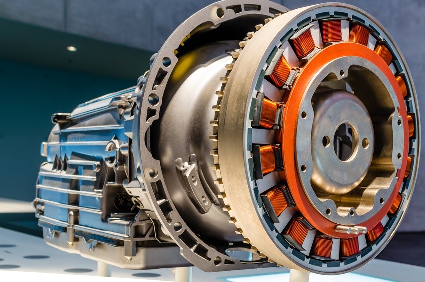
Image 1: Example of an electric oil pump
Image Source: Rheinmetall Automotive

But while the benefits are obvious, electrifying, in particular the oil pump, is technically complex: Engineers, not only wish to circulate the oil at a particular flow rate and pressure, but would like to intelligently match these to the engine requirements.

In order to optimize the performance it’s important that friction and pumping losses are minimized through careful control of the oil flow into different branches of the oil circuit while ensuring the correct pressure is available at all times.

Simulation relies on accurate testbed oil pressure and flow rate information

An electrically powered oil pump is made up of three subsystems – the pump, motor and electronic controller. Therefore the primary challenge of any new application development is the efficient integration of these modules so as to reduce the overall size and weight as well as the number of components, whilst optimizing performance.

The main function of the oil pump is to deliver a specified oil flow at an optimal pressure. For this reason, its design, which is an iterative process, starts with the ‘pumping gears’. For most applications the pump is required to deliver pressures in excess of 1 to 2 bar, often going as high as 10 bar.

As in most engine developments, a combination of simulation and real world testing is used to speed up the design. 

The design loop begins with the preliminary assessment of the volumetric efficiency based on experimental results collected on similar pumps and applications. These include pump speed, oil temperature, pressure and flow rate. 

It’s important that the information used for the estimation is accurate, therefore the data collection must be carried out using highly dependable, precise measuring equipment that can deliver accurate readings under the extreme conditions encountered in and around the engine.

To ensure accuracy and repeatability it’s important that only the best quality sensors are used when measuring the pressure. Not only must these pressure sensors provide reliable readings across a wide range of pressures and temperatures, but they must also withstand vibration.

Over many years STS have developed pressure sensors that meet OEM, first tier and specialist engine designers’ requirements in engine development. 

Developing an electric oil pump that outperforms the mechanical unit 

Armed with the information gathered on the hydraulic requirements at various flow rates, delivery pressures and oil temperatures, a preliminary design of the gears is finalized. Using Matlab’s  Simulink software, the information regarding the behavior of the physical system can be rationalized into an one-dimensional code. 

At this stage it’s important to note that to generate the required flow at a specified pressure, a rotational speed should be selected that facilitates the best packaging of motor and pump without creating cavitation or noise issues: Thus a typical speed range for continuous operation is usually between 1500 and 3500 rpm. 

In the next step, several designs can be generated using LMS Imagine. Lab’s Amesim software that optimizes the design parameters – for example the number of teeth and eccentricity, while satisfying all pressure, flow and temperature boundary conditions. 

After implementing the geometrical features of the calculated hydraulics and the interim design has been finalized the total torque required to drive the pump at critical working points can be calculated as follows: 

Mtot = MH + MCL + Mμ 

Where:

  • MH is the hydraulic torque due to the generation of required pressure and flow
  • MCL is the coulombian contribution generated where there are dry or lubricated contacts between sliding parts
  • Mμ is the viscous contribution due to the fluid movement inside clearances.

Once the design is completed, engineering prototypes are constructed for real world evaluation on an engine testbed. 

Once again oil pressure, flow rate and temperature are measured at various engine and pump speeds to validate the results obtained through simulation. If the results meet the specifications the development program is finalized and the project enters the industrialization phase. 

For optimal performance and durability it’s obvious that all measurements be accurately recorded, but the weight given to information generated by the pressure sensor possibly outweighs all others – insufficient pressure at any point can lead to a catastrophic failure; while excessive pressure wastes energy and could lead to problems with the oil seals.

Testing of proportional pressure regulators in hydraulic systems

Testing of proportional pressure regulators in hydraulic systems

When testing proportional pressure regulators as part of the development of complex hydraulic systems, high impulse capability and precision are required from the pressure measurement sensors employed.

In the development of new hydraulic systems, in automotive engineering, for example, a large number of components need to mesh together perfectly. In addition to experience gained and the models employed, test loops on the test bed play an important role here. Do the components arriving from suppliers meet the specifications? Are optimum results already achieved here in the overall system?

In oil-hydraulic systems such as vehicle clutches, the pressure valves used are of great importance. As mechanical components, they need to be thoroughly qualified in order to minimize negative effects such as overshoots or adverse flow effects. A valve that is not working optimally has a negative effect across the entire system. What pressure peaks can be expected and how do they affect the system? How must the valve be designed so that coupling processes are as smooth and vibration-free as possible? Precise pressure measurement plays a key role in clarifying these questions. Numerous tests are necessary before a harmonious overall system can be created and these negative effects can be largely eliminated. However, since these tests are not limited to the pressure valve alone, but instead carried out across the entire system, the demands upon the sensors used are correspondingly high.

Pressure measurement in hydraulic systems: Top performance is required

As an experienced partner for pressure measurement tasks in the Test & Measurement sector, STS has already supported a large number of projects related to the testing of proportional pressure regulators in hydraulic systems. Accordingly, we are very familiar with the high demands to be expected in the pressure measurement of pressure valves in oil-hydraulic systems.

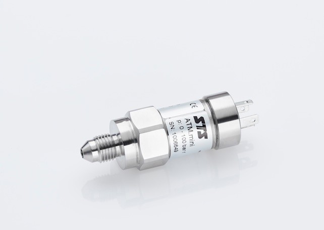
Due to the increasingly complex tasks involved in the qualification of hydraulic systems, space has now become a decisive criterion. These systems are nowadays equipped with a large number of sensors and so the smaller the better, therefore. In order to meet these requirements with regard to miniaturization of sensor technology, STS introduced the ATM.mini, a precision pressure transmitter with external dimensions of only 17.5 x 49 millimeters, which is now being used on numerous test beds. Flexibility with regard to installation is also required, since the sensors don’t just have to fit in terms of space. Also in terms of the process connections, there are always other specifications that have to be fulfilled. Finally, we can say from experience that the selection and installation of the sensor technology often follows the development of an application on the test bed and must be able to comply with the facts established there. For this reason, STS follows a modular design principle so that all products can be adapted to individual specifications. This, of course, also applies to the ATM.mini.

Apart from physical size, the “intrinsic values” are also decisive. If we return now to the example of hydraulic systems in automotive engineering, a very good impulse capability is essential for continuous measurements during the tests. It must be possible to record pressures dynamically within mere milliseconds of one another. In addition, this must proceed highly precisely over a relatively broad temperature range from -30 to 140°C. The non-linearity can often be a maximum of only 0.1 percent of the full scale measurement value (you can read more about precision here). This ultimately implies also that the pressure transmitter is largely insensitive to vibrations. Another important factor during the testing of components in a hydraulic system is that pressure peaks can always occur, the extent of which cannot be precisely determined in advance. For applications of this type, a pressure transmitter whose overload capability is many times the measuring range will thus be required.

The ATM.mini manufactured by us meets all of these requirements. Your advantages in summary:

  • pressure range from 0-1 bar to 0-100 bar
  • outstanding accuracy of 0.1% FS
  • compact design of outer dimension 17.5 x 49 millimeters
  • highest precision over the entire temperature range
  • compensated temperature range from -40 to 125 °C
  • no media incompatibility due to welded pressure port
  • individually adaptable solutions through modular construction
Pressure measurement of fuels – Material selection is decisive

Pressure measurement of fuels – Material selection is decisive

Aggressive liquids and gases pose a particular challenge to the pressure-sensing technology employed. For this reason, sensors are required which can be flexibly adjusted to the particular requirements. With the ATM.1ST product series, you will always remain on the safe side. 

A significant product characteristic of pressure transmitters is their modular construction. A variety of mechanical and electrical components can be co-assembled, according to application, to:

  1. optimally maintain the usage of matched pressure transmitters, and
  2. ensure a rapid implementation of the measurement setup.

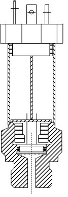
Figure 1: Assembly of a pressure sensor with O-ring measuring cell

The basis for this are high-quality measuring cells of a piezoresistive nature, which are sealed using O-rings. This construction allows for a multitude of combinations. Dependent upon usage within the pressurized medium, various O-ring materials are employed (Viton, EPDM or Kalrez) to optimally tailor the pressure sensors to that particular application.

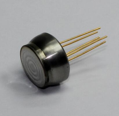
Figure 2: Example of a metal-seating pressure measurement cell

For application in aggressive media such as fuels (diesel, gasoline, …) or in high-pressure operations, however, sealing with O-rings becomes unsuitable. In such environments, the measuring cell has to be welded together with the pressure port. For this reason, an elastomer-free metal-sealing variant was developed for applications in fuels: The ATM.1ST product range.

These elastomer-free (metal-sealing) versions can be offered in the most diverse of mechanical designs. In the accuracy class of 0.05% FS, the pressure transmitter is available in nominal pressure ranges from 0…20  bar up to 0…100 bar and with an output signal from 4 – 20 mA.

In the 0.1% accuracy class, the pressure sensors are offered in nominal pressure ranges from 0…20 bar up to 0…700 bar and in versions of 4-20 mA or 0 – 5/10 V.

The analog transmitters are calibrated in two temperature ranges, -25…125°C (standard) or -40…125°C (optional). Across both temperature ranges, a Total Error Band of < 0.4% FS is guaranteed.

Featuring a shortened form, robust housing and a very high flexibility, the ATM.1ST product range allows end users to configure these pressure sensors according to the prevailing requirements. Regardless of pressure port or electrical connection, a broad range of possibilities for mechanical mounting are available.

With this convincing technical specification, these pressure sensors are ideally suited to various fields of application in measurement technology or plant and mechanical engineering, as well as in the equipping of test beds or calibration facilities.

Landing gear hydraulic pressure testing

Landing gear hydraulic pressure testing

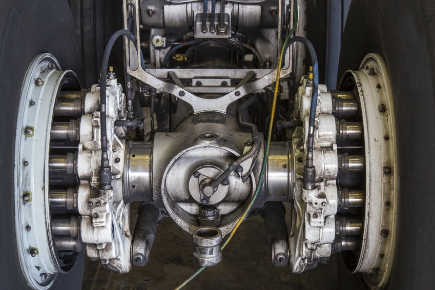
Imagine, you’re a pilot in your own plane, cruising on a beautiful day. You line up your approach to the airstrip and flip the switch to actuate the hydraulics for the landing gear to deploy. Suddenly, a low pressure warning appears and the landing gear won’t deploy. Now you have a problem! Amongst the grumblings under your breath will likely be a few unsavory comments about the engineers that designed that hydraulics system. Well, that’s us; and that pilot we’re imaging, that’s our client. They deserve to have a reliable and flawless landing, don’t they? Therefore, it’s on us to design a hydraulic system that can achieve just that, but how? Well the specifics, components, and design are across the board from plane to plane; however, there is one point that is guaranteed to be universal for our endeavors, hydraulic pressure testing! We will all test and test, then try to damage the system and test again! So naturally, we need a pressure sensor that can consistently and accurately record the conditions in our hydraulics system as we fine-tune all the details. Well we have a sensor that can do exactly that and for the remainder of this article we will explore the capabilities of the STS high precision pressure transmitter ATM.1ST.

As we begin to develop our hydraulic pressure measurement regimen, we must first determine the exact data we wish to collect. As we all know, ‘pressure’ is a very broad term to use in a hydraulic system and has very little meaning on its own. Are we referring to the accumulator pressure, pump delivery pressure, the regulator pressure, or perhaps the relief pressure? That decision is up to you, but thankfully STS has developed a series of pressure transmitters that can collect data in any of these sub-components. What do we mean by that? Well, the STS high-precision pressure transmitter ATM.1ST is designed with a modular and adaptable approach. We, as the engineers, can cherry-pick the features and capabilities for every sub-component of the sensor to ensure that every last one is perfectly suited for the environment that it will encounter over the course of the test.  

Let us now break down these sensor modules for a moment. First, we have our choice of materials for nearly every part of the sensor to ensure strength and durability. For example, the housing and transducer can be constructed from stainless steel or titanium depending on the burst pressure we must withstand amongst other factors, and this will in turn be determined from your particular hydraulic setup.  

However, our material selection is not limited to the housing. We also have the power to pick and choose the seal material for our sensor. The selections in this department include Viton, EPDM, Kalrez, and NBR. Naturally, the hydraulic fluid will be consistent throughout the landing gear system; therefore, once we determine the seal material that will have the best interaction with the fluid that particular material can be guaranteed to function throughout the system. Another factor to be kept consistent throughout our test setup is the overall accuracy of our pressure sensors. Luckily, STS grants us leverage over that characteristic as well with the high precision sensors of the ATM.1ST line. We have 0.25%, 0.1%, and 0.05% FS to ensure that our data collection is both accurate and consistent throughout the entirety of the test.  

The last two modular selections that are prudent to our landing gear testing are the electrical and process connections. In the electrical world we have FEP, PUR, and PE cables to select from, along with a range of different connectors. As for process connections, our diaphragm, DIN, and other specifications are entirely at our discretion. While the sheer volume of different combinations may seem slightly overwhelming at face value, they grant us the capability to piece together a pressure sensor that will slide into our test setup seamlessly without driving any special setup or design changes.  

Now let us return to our landing gear testing. As we develop and test the hydraulic system to achieve flawless landing gear operation we are going to need data from several locations within the system. As mentioned above, we have the accumulator that acts as a damping device of sorts to smooth out any pressure variations within the system. Naturally, we as the engineers need to know what those variations are exactly. Therefore this seems to be a perfect location for a test sensor!  

On the subject of pressure maintenance, the regulator also falls squarely into this category. As the pressure fluctuates due to valves opening and closing or any irregularities in the system, the regulator kicks in to ensure that the system pressure remains within the specified range. Once again, this is another crucial component to keep an eye on as we develop our landing gear, and we now have the resources to select a perfectly customized pressure sensor to slide into the system and accomplish just that with precise measurements and easy to install electrical connectors. 

In review, we are tasked to develop a reliable landing gear system via a rigorous curriculum of testing. However, the hydraulic system of such a mechanism is extremely diverse in terms of components and potential locations for sensors. Thankfully for us, STS has produced a reliable little powerhouse in the ATM.1ST pressure sensor that allows us to have nearly complete jurisdiction over all aspects of the sensor; including materials, accuracy, sealing, and electrical connectors. Long story short ladies and gentlemen, this high-accuracy sensor allows us to devise a streamlined and robust testing process where our test sensors complement our setup, and do not dictate it.

Subscribe To Our Newsletter

Join our mailing list to receive the latest news and updates from our team.

You have Successfully Subscribed!