Better defense against climatic anomalies using dependable level sensors

Better defense against climatic anomalies using dependable level sensors

Over the past few years, Russia has been increasingly struggling with environmental disasters caused by extreme weather conditions. This has not only led to massive material damage, but has also cost human lives. An extensive structural program for better weather forecasting is now destined to diminish those risks and also to support research on climate change.

Weather anomalies, such as the extensive drought of 2010 or the heavy flooding in the Amur region in 2013, generated major attention and concern within Russia, as well as beyond. The Federal Service for Hydrometeorology and Environmental Monitoring (Roshydromet) is responsible for high-precision weather forecasts in Russia and is now to be further bolstered under the terms of the Hydrometeorological Services Modernization Project-II. A little over 139 million dollars has been invested for this purpose.

This large-scale modernization project will be supporting Roshydromet in providing the Russian population, as well as municipal authorities, with reliable and up-to-date information on weather, hydrology and climate. At the same time, Russia is also to be better integrated into the global system of meteorological services.

The individual project measures include:

  • Strengthening of information and communication technologies for providing data on weather, climate and hydrology,
  • Modernization of the observation network,
  • Consolidation of institutions,
  • Optimized access to Roshydromet data and information,
  • The improvement of disaster protection.

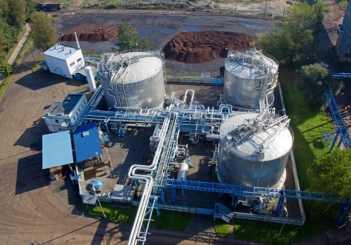
With the modernization of Roshydromet’s hydrological observation network in the Lena, Jana, Indigirka, Vilui and Kolyma rivers, special attention has been paid to monitoring technology, which, largely maintenance-free, performs reliably in difficult to access areas and also under harsh conditions such as permafrost.

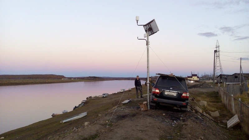
Fig. 1: Overview of the monitoring sites

Some of the water level sensors essential here were provided by STS and, in collaboration with the Russian partner company Poltraf CIS Co. Ltd., installed at 40 hydrological monitoring stations. The project itself comprised the following requirements:

  • The permanent monitoring of water levels and temperatures, as well as the measurement of rainfall and snowfall. This also includes the installation of surveillance cameras to keep the formation of ice at strategically important points in view.
  • The automatic and error-free transmission of data via GPS or satellite.
  • An alarm function when exceeding defined limits.
  • A server solution for storing the collected data, including a software for the visualization, evaluation and processing of that data.
  • A simple-to-install and easy-to-use technology that will perform for years on end without major maintenance.
  • A professional preparation of the actual monitoring locations.

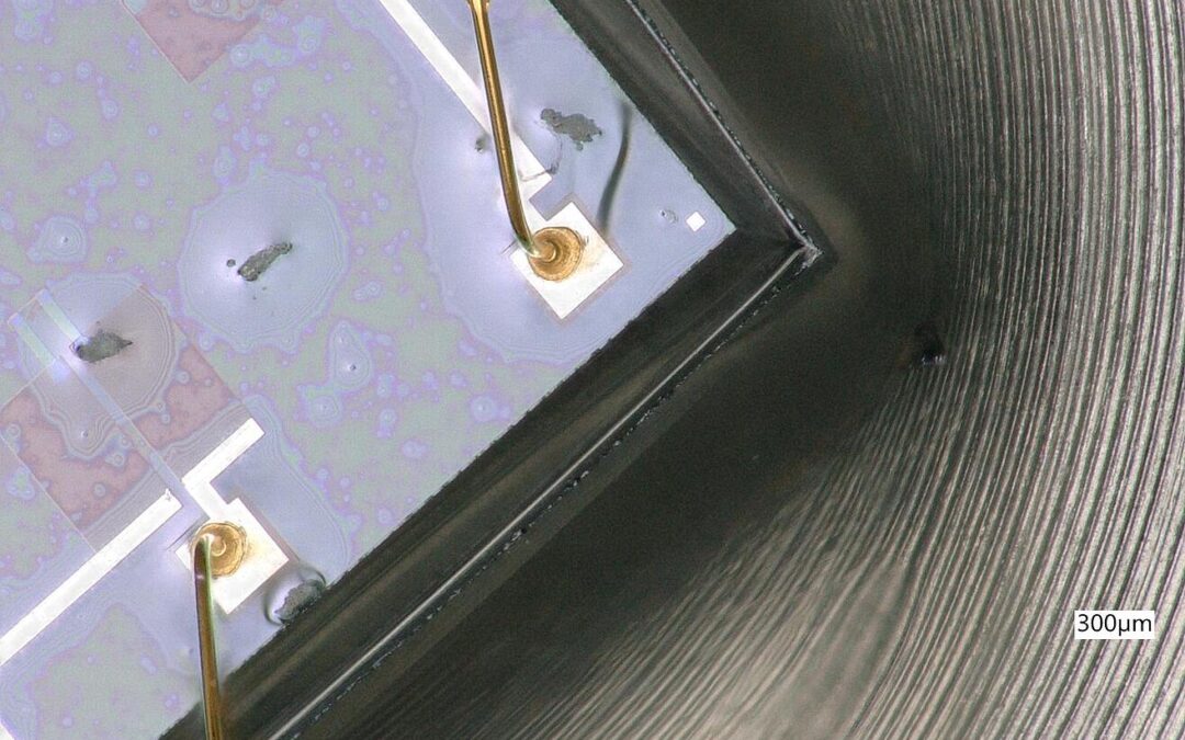
To meet this demanding assignment, the DTM.OCS.S/N/RS485 Modbus sensor, including others, has been employed. These digital level probes actually measure both level and temperature. The harsh conditions are addressed by its robust design and permissible ambient temperatures of -40 to 80 degrees Celsius, whilst an accuracy of ≤ 0.03% FS ensures precise results at critical measuring points.

Some further advantages of this digital level sensor in brief:

  • High-precision digital level sensor for easy integration into standard Modbus networks
  • Individual adaptation to application through modular design
  • Highest precision over the entire temperature range due to electronic compensation
  • Adjustment of zero offset and measurement range via Modbus
  • Extended long-term stability of measuring cell
  • Sensor can be recalibrated
Hydrostatic level monitoring of tanks on piezoresistive basis

Hydrostatic level monitoring of tanks on piezoresistive basis

Hydrostatic pressure measurement is one of the most reliable and simplest methods for fill level monitoring in liquid-carrying tanks. In the following, we explain how hydrostatic level monitoring works and what users should consider here.

In hydrostatic level measurement, the filling level of a liquid in a container is to be measured. In this case, the force of weight acting on the pressure transducer installed at the bottom of the container is measured. The weight force in this context is termed the liquid column. It increases in proportion to the filling level and acts as a hydrostatic pressure on the measuring instrument. The specific gravity of the fluid must always be considered in hydrostatic level monitoring. The filling height is thus calculated with the following formula:

h = p/sg

In this formula, h stands for the filling height, p for the hydrostatic pressure at the base of the tank and sg is the specific gravity of the liquid.

The actual quantity of fluid plays no role in hydrostatic level monitoring, since only the filling height is decisive. This means that the hydrostatic pressure is identical in a 200 liter tank narrowing towards its base and in a straight sided tank containing 150 liters of liquid, as long as the liquid and the fill height are identical (3 meters, for example).

The simplest application of hydrostatic pressure measurement is when the liquid concerned is water, since the specific gravity can be disregarded altogether here. When a fluid other than water is involved, the pressure transmitter has to be correspondingly scaled to compensate for the specific gravity of that liquid. Once this has been done, the fill level can be determined, as with water, via the hydrostatic pressure on the bottom of the tank. It becomes more complicated when different liquids are used in a single tank. In this case, not only the hydrostatic pressure at the bottom of the tank must be measured, but at the same time the specific gravity of the respective fluid also. We will leave aside the latter case at this point and instead consider hydrostatic pressure measurement in both closed and open tanks.

Hydrostatic pressure measurement in open and closed tanks

With open tanks, it does not matter whether they are above ground or set within it, as long as they have an opening that provides for a balanced air pressure inside and outside the tank. The measurement of the hydrostatic pressure can be carried out without further adjustments at the bottom of the tank. If measurement at the bottom of the tank is not possible, the filling level can also be found by means of a submersible probe, which is fed into the tank with a cable from above.

In closed tanks, higher gas pressures often prevail than in the atmosphere surrounding the tank. This gas layer above the liquid increases the pressure on the liquid itself. As a result, the liquid can flow off more quickly and there is also less loss due to evaporation. Tanks sealed from the ambient air are therefore frequently used in the oil and chemicals industries. The gas layer pushing down on the liquid also acts indirectly on the pressure transducer at the bottom of the tank and must therefore be taken into account in order to determine the correct filling level (a higher filling level than the actual would be indicated through this increased pressure). In closed containers, two pressures would therefore have to be measured: The gas pressure and the pressure at the bottom of the tank. The hydrostatic pressure of the fluid results from the difference between the measured gas pressure and the pressure measured at the base. This difference can then be converted into an indication of the fill level of the tank. For this type of application, a differential pressure sensor is generally used.

Concluding remarks

In hydrostatic level monitoring of tanks, two factors must always be considered: The type of fluid and the type of tank. The simplest application would be the monitoring of water levels in open tanks, since no adjustments have to be made for this constellation. If, however, a different liquid is involved, then the specific gravity of that liquid must also be taken into account. In addition, a measuring instrument is to be selected that can withstand the properties of the medium concerned. Whereas for most liquids stainless steel is sufficient as a housing material, highly corrosive media may also require different materials.

Integration of piezoresistive measuring cells into existing applications

Integration of piezoresistive measuring cells into existing applications

The core element of every pressure transmitter is the pressure measurement cell. With piezoresistive pressure transmitters, this equates essentially to the Wheatstone bridge measuring arrangement. The primary pressure measurement takes place here by way of deformations to the strain gauges. This piezoresistive measuring cell can also be integrated into existing applications such as pressure switches or pressure regulators, should this be necessary. Various possibilities exist to this end.

The most common reason for the need to integrate a sensor cell instead of a pressure transmitter into an existing application is a lack of space. In hydraulic valves, for example, there are only a few cubic centimeters of space. The integration of an entire pressure transducer is therefore not usually possible. Because of insufficient space, some users opt to employ an external sensor, which is then flange-mounted to the existing application. This approach, however, is cumbersome and not as optimal as the integration of separate measuring cells into the application.

In the selection of suitable measuring cells for individual applications, the same questions apply by and large as with the selection of an entire pressure transmitter.What needs to be established, among other things, are the pressure range to be measured, the temperature conditions and also the relevant media compatibility. In the employment of piezoresistive measuring cells into existing applications, three further selection criteria can be added: These are the mechanical and electrical considerations for integrating the sensor cells.

The mechanical selection criterion relates to actually building the measuring cells into the relevant application. Depending upon requirements, these possibilities remain open:

  • screw in
  • weld on
  • plug in
  • wedge in

On the electrical side, it must be determined which electronics are used in the application to provide the electrical signal transmission. In some circumstances, it may be that the electronics existing in the application are not equipped for the integration of pressure measurement cells. In this case, an electrical signal conversion would have to be separately integrated.

We now arrive at a real life example: An STS customer wanted to retrofit an existing precision high-pressure control valve for test bench applications with the option of pressure measurement. Since an entire pressure transmitter could not be integrated into the valve, a single pressure measurement cell had to be opted for. The demands here were that it had to display pressures up to 600 bar and it should be designed for a signal output from 0 to 100 mV/V at a supply of 10 V.

The solution selected was a measuring cell with stainless steel pressure port and miniature compensation technology. This could be screwed into the valve body below the already existing cover in a space-saving manner and also shielded from external influences. The assembly height after mounting on the valve body came to under 30 mm (including bending radius of cord strands). Apart from its minimal dimensions, there was one additional feature: The zero position and range were individually adaptable by the user with a potentiometer.

Measuring cell with stainless steel pressure port for implementation on a high-pressure control valve

Consultancy is key

Piezoresistive measuring cells are the core competency at STS. They are fully manufactured in-house, display pressure ranges from 100 mbar to 1,000 bar and are available in the materials of stainless steel, titanium and Hastelloy®. This means that, in principle, they can be employed for almost any conceivable measuring task. In collaboration with our engineers, customers receive an extensive consultancy on the integration of suitable measuring cells into existing applications.

Strain gauges in pressure measurement technology

Strain gauges in pressure measurement technology

Strain gauges are measuring devices that change their electrical resistance through mechanical deformation. They are used in a variety of measuring instruments, which, besides scales and load cells, also includes pressure sensors.

Pressure sensors rely on several physical variables, including inductance, capacitance or piezoelectricity. The most common physical property by which pressure transmitters operate, however, is the electrical resistance that can be observed in the metallic deformation, or piezoresistive effect, of semiconductor strain gauges. The pressure is determined by a mechanical deformation, where strain gauges are attached to an elastic carrier. It is important here that the strain gauges can follow the movements of this carrier. If a pressure acts on the carrier, the deformation arising brings about a change in cross-section of the conductor tracks, which in turn causes a shift in the electrical resistance. It is ultimately this change in electrical resistance that a pressure transducer records and from which the pressure can then be determined.

Figure 1: Strain gauges deform under pressure

The deformation acting upon the conductor will thus cause it to change in length (Δl). Since the volume remains the same, it is the cross-section and thus the resistance R that changes:

ΔR/R = k • Δl/l

The change in resistance (ΔR) is proportional to the change in length (Δl), and the proportionality factor (k) will depend on both the geometry and the material properties. While ‘k’ will be 2 for metallic conductors, it can also be very high in semiconductors. Because of these relatively high ‘k-factors’ for semiconductors, these are more sensitive and can therefore measure even the slightest of pressure changes. Temperature dependency, however, also increases as a result of this.

The change in resistance in metallic strain gauges results from dimensional changes (geometry). In semiconductor strain gauges, however, the change is due to alterations in the crystal structure (piezoresistive effect).

The evaluation of the resistance change triggered by a pressure-induced deformation then takes place via a bridge circuit. For this purpose, the strain gauges are connected up to form a Wheatstone bridge (Figure 2). Two of the strain gauges are placed in a radial direction and two in a tangential one. It is thus so that two become stretched and two become compressed under deformation. In order for temperature effects to be compensated and for the signal to be as linear as possible, it is important that the strain gauges have the exact same resistances and are arranged in an exact geometry.

Figure 2: Bridge circuit

Metallic strain gauges

Among metallic strain gauges, we must differentiate between the foil and thin-film varieties.

Foil strain gauges consist of rolled foil, only a few microns thick. Constantan is normally used as the material here, but Karma and Modco can also be employed, especially if a larger temperature range is needed or the temperatures are below -150 °C. Constantan has a very low ‘k-factor’ of 2.05 and is therefore not very sensitive. Considering this, the material displays a lowered temperature dependency, which is also why it is most often used in foil strain gauges.

Foil strain gauges are more likely to be used in load cells. Often they are not sensitive enough to be pressure transducers, since values of less than one bar cannot be recorded with them. Their temperature range is also relatively limited, and, depending on the version, temperatures of even 80 °C should not be exceeded.

Thin-film strain gauges are produced by the so-called thin-film technique, by, for example, vapor deposition or sputter coating. The manufacturing process is more complex here and also more expensive than for foil gauges. On the other hand, however, a temperature range of 170 °C is possible, with their long-term stability also being very good.

Metallic thin-film strain gauges provide for stable over the longer term, but also quite expensive, measuring instruments. It holds true that the lower the pressures to be detected are, the higher the manufacturing cost will be. Low pressures of less than 6 bar can only be detected at a poor accuracy.

Semiconductor strain gauges

Semiconductor strain gauges operate by the piezoresistive effect. The material used in most cases is silicon. Semiconductor strain gauges tend to be more sensitive than the metallic variety. They are also usually separated from the medium by a separation membrane, with the pressure being passed on via a transfer fluid.

Figure 3: Piezoresistive measuring device

In semiconductor materials, the piezoresistive effect is about fifty times more pronounced than with metallic strain gauges. The semiconductor strain gauges are either glued to a carrier or directly sputter-coated onto it. The latter enables an intense bonding and assures freedom from hysteresis, as well as a resistance to aging and temperature stability. Although the piezoresistive effect is not exclusive to the semiconductor strain gauge, the term “piezoresistive pressure sensor” has come to be used for instruments where the elastic structure deforming under pressure and the resistors are all integrated into one chip. Piezoresistive pressure transducers can be made small in size and (apart from the membrane) without any moving parts. Their production is based on normal semiconductor fabrication methods. At the same time, there is the possibility of integrating the resistors with the elastic membrane deforming under pressure all into one chip and thus produce a full pressure measurement cell in the size of just one chip.

Piezo thin-film strain gauges are attached to a silicon carrier and separated from the carrier by an insulating layer. This increases the manufacturing requirement and thus also the price, but temperature ranges from -30 °C to 200 °C are possible here. Thanks to the highly elastic properties of silicon, only a low hysteresis can be expected with these. It is the high ‘k-factor’ that achieves the high sensitivity, making piezoresistive pressure transmitters the first choice for the smallest of pressure ranges on the mbar scale. In addition, devices of tiny dimension can be produced, which has a positive effect on the scope of potential applications. Also, the long-term stability and EMC compatibility is very good, with the latter, of course, depending upon carrier material. Temperature compensation, however, requires a little more effort, but even this challenge can also be overcome quite easily. You can read more about temperature compensation here.

Thick-film strain gauges are printed onto ceramic or metallic membranes. With a thickness of 20 microns, they are up to 1,000 times thicker than thin-film strain gauges. Because of their low production requirements, these are cheaper in price, but not very stable longer term due to the aging of their thick film.

Summary: The type of strain gauge used has a major influence on the measuring instrument. Factors such as price, accuracy and long-term stability play an important role in choosing the right pressure transmitter. In our experience, pressure transmitters with piezo thin-film strain gauges have proven to be the most efficient, because, thanks to their sensitivity, they can record wide pressure ranges at high accuracy, whilst also exhibiting good long-term stability.

Fouling as a cause of drift in pressure sensors

Fouling as a cause of drift in pressure sensors

We all know the saying that ‘you can’t make an omelet without breaking eggs’. In the development of new combustion engines specifically, this means that soot particles or oil residue can contaminate the sensors employed.

The consequence of such soiling amounts to increasingly inaccurate readings. When, for example, the exhaust system of a new combustion engine is being monitored with pressure transducers, more and more fine dust will settle on the diaphragm of the sensor over time. The membranes of piezoresistive pressure sensors are very thin so that they can deliver high-precision measurement results. But when a layer of soot forms on this over time, it reduces the overall sensitivity of the pressure transducer.

Protecting pressure transmitters from particulate matter

End users make note of this drift in the sensor by performing reference pressure measurements. They will find considerable differences between the values of this reference pressure gauge and the soiled sensor itself. Often, however, the readings experienced by users reveal when the measured signals deviate too far from the expected results. Strong fluctuations in these measured values can also be an indicator of contamination.

STS generally recommends that users whose sensors are exposed to dirt should service them after a maximum of 100 operating hours. In addition, users can also try to protect the sensor as much as possible from contamination. There are two common methods used here.

Method 1: Protective foil

The first method does not replace maintenance of the sensor after a maximum of 100 hours, but it does simplify cleaning and also preserves the membrane. In this case, a very thin, metallic protective foil is applied to the membrane to protect it from soiling. After a maximum of 100 operating hours, this film is then simply peeled off and replaced with a new one.

Method 2: Cooling adapter

This method allows users to kill two birds with one stone. By screwing a cooling adapter or a climatic valve to the front end of the pressure port, the membrane is now largely protected from soiling. The climatic valve opens only when there is actually something to be measured. Where no permanent pressure monitoring is required, this can be a good method for minimizing the degree of contamination to the sensor employed.

At the same time, a constant sensor temperature can also be ensured via this cooling element. Besides membrane contamination, temperature also has an effect on the measuring accuracy of piezoresistive pressure transducers (More on the influence of temperature on the accuracy of pressure sensors can be found here).

Cleaning of pressure sensors from oil contamination

Contamination with heavy oil particularly comes about in the development of marine engines. The additives incorporated become especially deposited on the membrane and can even damage it. These residues reduce the sensitivity of the pressure transducer and regular servicing must be observed here also.

To keep soiling and the consequences thereof as minimal as possible, consideration should be given to the nature of the pressure sensor at its selection. A stainless steel membrane is recommended, which is front-flush and has no channels in which even the smallest of deposits can gather. The smoother the better also applies here, because on a rough membrane undesired particles will actually deposit faster and these are also more difficult to clean.

To clean a soiled pressure sensor, it must be removed from its application. Isopropanol (IPA) is recommended as the cleaning agent here. While the sensor housing requires no special caution, the membrane should be treated without any firm pressures by using, for example, cotton swabs. Under no circumstances should compressed air be used, since the membranes are very thin and, when too much pressure is exerted, deformations can occur.

Subscribe To Our Newsletter

Join our mailing list to receive the latest news and updates from our team.

You have Successfully Subscribed!