Deprecated: Hook wp_smush_should_skip_parse is deprecated since version 3.16.1! Use wp_smush_should_skip_lazy_load instead. in /home/xepoxenu/www/new.stssensors.com/wp-includes/functions.php on line 6078
Pressure Transducer Archives - Page 2 of 5 - STS Switzerland (EN)
Deprecated: Hook wp_smush_should_skip_parse is deprecated since version 3.16.1! Use wp_smush_should_skip_lazy_load instead. in /home/xepoxenu/www/new.stssensors.com/wp-includes/functions.php on line 6078
Oil prospecting below the seabed

Oil prospecting below the seabed

Science has a more accurate picture of the surface of Mars than of the seabed. An exact knowledge of the nature and layout of the ground below water is necessary for a variety of reasons, including shipping safety, research purposes (archaeology, marine studies) and exploration aims. This also includes the exploration of oil deposits under the seabed.

To identify possible oil reserves below the oceans, the geological characteristics of the seabed must be analyzed. Since this is generally a question of areas very difficult to access and at great depths, the seabed is mapped out using sound by a process known as seismic reflection.

Oil prospecting by the seismic reflection method

In seismic reflection, artificially created seismic waves are examined. These waves spread out under water and, similar to a beam of light at its optical limits, become partially refracted and reflected as they strike upon strata boundaries. At this point, the proportion of the wave reflected at the boundary surface is dependent upon the speed as well as density differences between adjoining strata. These reflected waves then return to the water surface. Both the energy and the time expenditure of this wave motion are recorded by geophones. When the recorded data is then processed, it becomes evident at which depth the respective strata boundaries are to be encountered.

The most common form of seismic reflection is termed the Common Midpoint method (CMP). The aim here is to obtain a series of traces reflecting from the same midpoint. These traces are then stacked. Before this, however, a correction for time delay is essential, which is termed Normal Moveout. The different reflection points of the traces are corrected here in such a way that they appear in the stack section at the right time and in the correct position.

Common Midpoint method: Accurate pressure measurement is essential

In the practice of oil prospecting, a specially equipped vessel is used, which drags numerous measuring cables behind it, in this case named streamers, which can be several kilometers long. These streamers are equipped at regular intervals with hydrophones for recording the reflected waves. To generate those waves, a sound source is installed at the beginning of the streamer. In order to obtain the most accurate results, an awareness of the exact position (depth) of the hydrophones is essential. For this purpose, each individual hydrophone is equipped with a pressure measuring cell.

In oil prospecting below the seabed, the positioning of the hydrophones is often performed by pressure measuring cells made by STS. Since absolute precision is required in this complex and computationally intensive process, the measuring technology employed must meet stringent requirements. Because the streamers run only a few meters below the water surface, the measuring cells must be capable of displaying pressures from 0 to 15 bar. But because of their proximity to the water surface, the actual measuring range only goes up to 2 bar (absolute). The required accuracy in this particular range amounts to less than 0.3 percent total error.

Further requirements that STS has fulfilled in the development of these measuring cells according to customer requirements were, firstly, the small dimensions of 12 mm x 13.8 mm. Additionally, when the ship comes to a standstill, the hydrophones sink down. To withstand the pressures at a great depth and to remain further functional, the measuring cells must also withstand an overload pressure of 100 bar. And since this is a salt water application, titanium is used for the housing of the pressure measuring cell.

Hydrogen embrittlement in steel

Hydrogen embrittlement in steel

The sensor chip of piezoresistive pressure transducers is usually surrounded by a steel membrane. For the housings of these measuring instruments, stainless steel is also used in most applications. But should contact with hydrogen occur, this material can become brittle and then crack.

Hydrogen embrittlement affects not only steel, but also other metals. This is why the use of titanium offers no alternative in regard to hydrogen applications.

What is meant by embrittlement?

Hydrogen embrittlement refers to a loss of ductility in the material. Ductility describes the property of materials to plastically deform under stress before they finally fail. Depending on its type, steel can deform by more than 25 percent. Materials that do not have this ability are termed brittle.

But ductile materials can also become brittle, or frail. When this embrittlement of the material is the result of hydrogen absorption, this is then termed hydrogen embrittlement.

Hydrogen embrittlement occurs when atomar hydrogen diffuses into the material. The prerequisite for hydrogen embrittlement itself is usually hydrogen corrosion.

Hydrogen corrosion, also known as acid corrosion, always takes place whenever oxygen deficiency exists and metal comes into contact with water. The end product remaining from this redox reaction is pure hydrogen, which then oxidizes the metal. The metal goes into solution as ions and causes the material to be evenly degraded.

The hydrogen released by this redox reaction diffuses into the steel due to its small atomic size of only about 0.1 nanometer. The hydrogen directly occupies the metal lattice of the material as atomic interstitials. Lattice imperfections arising here then increase the absorption capacity. This leads to a chemical fatigue in the material, which can ultimately cause cracks from the inside to the outside, even at low loads.

Hydrogen and pressure transmitters

Because of its very tiny dimension, hydrogen can not only penetrate the material, but can actually penetrate it completely. For this reason, not only an embrittlement of the material can occur. The metal membranes of piezoresistive pressure sensors are very thin – the thinner they are, the more sensitive and accurate the sensor becomes. If hydrogen diffuses into and through the membrane (permeation), it can then react with the transfer fluid surrounding the sensor chip. As a result, changes in the metrological properties of the measuring bridge occur due to hydrogen adsorption. At the same time, an increase in pressure can also occur as a result of these deposits, with outcomes ranging from a buckling of the sensor membrane through to its complete destruction.

Besides using a thicker but somewhat more inaccurate membrane, this process can be greatly retarded by using a gold alloy and the unit lifespan thus optimized. You can read more about this here.

Lifespan optimization of pressure transmitters in contact with hydrogen

Lifespan optimization of pressure transmitters in contact with hydrogen

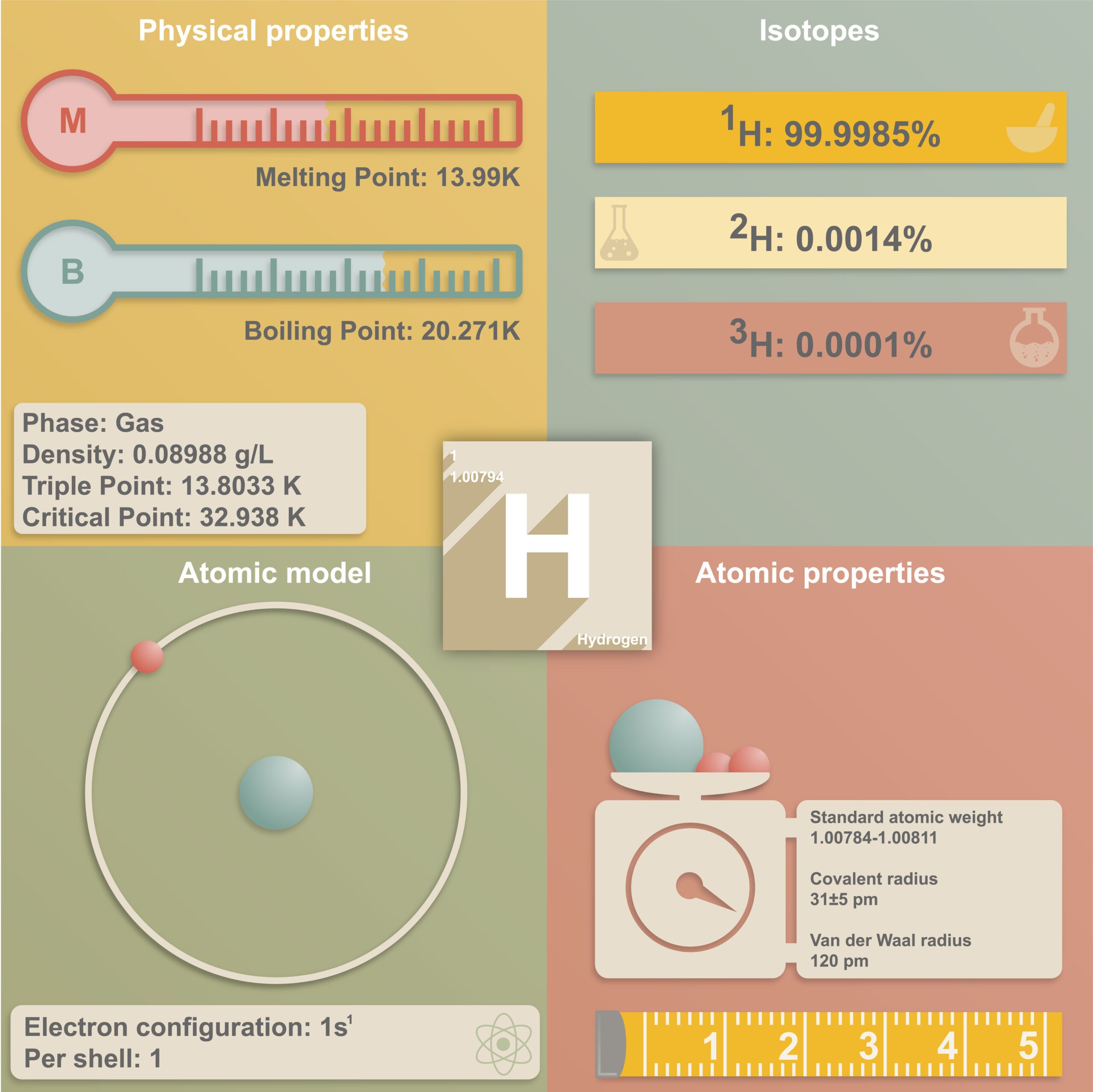
Hydrogen atoms are extremely tiny and because of this property can even penetrate solid materials in a process known as permeation. Over time, pressure transmitters become inoperative due to this process. Their lifespan can however be optimized.

In piezoresistive pressure transmitters, the sensor chip is enveloped in a fluid, usually oil. This section is in turn enclosed by a very thin, 15 to 50-μm-thick, steel membrane. Because of the miniscule atomic dimension of hydrogen, the gas can diffuse through the crystal lattice of metals (see infographic). Over time, this penetrating gas leads to a no longer tolerable zero shift in the signal arising and the steel membrane bending outwards. The pressure sensor thus becomes unusable.

Overview of hydrogen properties

Infographic: malachy120///AdobeStock

Pressure sensors come into contact with hydrogen in a wide array of applications, be it in the monitoring of hydrogen tanks themselves, in submarines or in the automotive sector. Especially in the latter case, hydrogen is being increasingly used in the development of alternative drive systems. Many manufacturers have been working for several years on models incorporating fuel cells and some cities have already opted for hydrogen buses in public transport. The advantages are not to be dismissed, since only hydrogen and oxygen are required as source materials. Through a chemical reaction, energy in the form of electricity is produced, with no exhaust gases created at all (the combustion product is water vapor). Furthermore, hydrogen, as opposed to fossil fuels, is available in inexhaustible quantities. Development is already well advanced and there are now models, which consume only 3 liters of hydrogen over 100 kilometers, whilst distances of up to 700 kilometers with one tank filling are, in part, already possible.

In this branch, high-performance, high-precision pressure transmitters are necessary, which monitor the hydrogen tanks of the vehicles. More specifically, the pressure and temperature inside the hydrogen tank of the vehicle must be monitored. Pressures of up to 700 bar can arise here, but a broad temperature range must also be covered. It is imperative, of course, that the pressure transmitters used perform their duty over an extended period of time at the required precision. To optimize the lifespan of sensors in hydrogen applications, several influencing factors must be considered:

  • Pressure range: The gas flow through the sensor membrane is proportional to the square root of the gas pressure. A ten-fold-lower pressure increases the lifespan of the sensor by about 3 times.
  • Temperature: The gas flow through the sensor membrane increases at higher temperatures and depends upon the material constant.
  • Membrane thickness: The gas flow is inversely proportional to the membrane thickness. The use of a 100 μm instead of a 50-μm-thick membrane doubles the lifetime of the sensor.
  • Membrane area: The gas flow is directly proportional to the membrane surface area (the square of the membrane diameter). With a Ø 13 mm instead of an Ø 18.5 mm membrane, the lifespan of the sensor doubles.

Since high pressures and broad temperature fluctuations can occur inside the hydrogen tanks of vehicles, the lifespan of the sensors cannot be influenced by these two factors. The factors of membrane thickness and membrane area also only promise a limited remedy. Although the lifespan can be improved by these factors, it is still not yet optimal.

Gold coating: The most effective solution

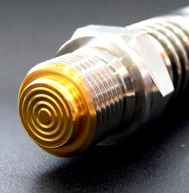
The permeability of gold is 10,000 times lower than that of stainless steel. With the gold coating (0.1 to 1 μm) of a 50 μm steel membrane, hydrogen permeation can be suppressed significantly more effectively than by doubling the membrane thickness to 100 μm. In the first scenario, the time for a critical hydrogen gas volume to accumulate in the interior of the pressure sensor can be increased by a factor of 10 to 100, whereas in the second example only by a factor of two. The prerequisite for this is gapless and optimized welding, as well as a largely defect-free coating.

Image 1: Example of a pressure transmitter with gold coating

Because of these properties of gold regarding the permeability of hydrogen, STS uses gold-coated stainless steel membranes as standard in hydrogen applications.

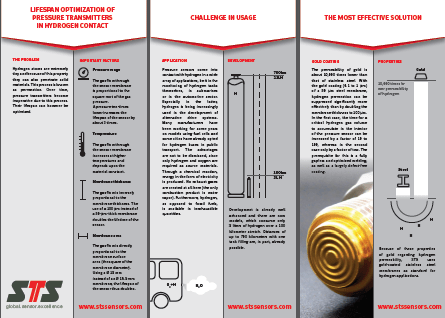
Downlaod our free infographic on the subject:

Image 1: Example of a pressure transmitter with gold coating

Mapping boost pressure on downsized turbo engines is the key to success

Mapping boost pressure on downsized turbo engines is the key to success

To meet ever tightening emissions legislation across the world OEMs are turning to downsized Spark Ignition engines. While these smaller engines consume less fuel and produce significantly lower emissions they require forced induction to deliver the performance drivers have come to expect from modern passenger vehicles.

The driveability of these downsized turbo engines must at least equal the performance of their naturally aspirated equivalents. This requires full boost pressure at low engine speeds without running out of steam at high speed, which can only be achieved with a sophisticated boost pressure control system.

The main problem with these forced induction spark ignition engines is the precise control of the air-fuel ratio near stoichiometric values at different boost pressures. At low speeds, these engines are prone to knock under medium to high loads.

Modern pressure control systems

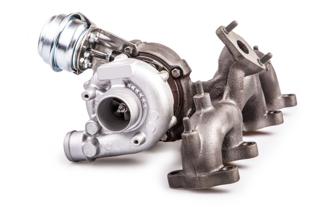
Controlling the turbine-side bypass is the simplest form of boost pressure control.

Once a specific boost pressure is achieved, part of the exhaust gas flow is redirected around the turbine via a bypass. A spring-loaded diaphragm usually operates the wastegate which opens or closes the bypass in response to the boost pressure.

In recent times manufacturers have turned to variable turbine geometry to regulate boost pressure. This variable geometry allows the turbine flow cross-section to be varied to match the engine operating parameters.

At low engine speeds, the flow cross-section is reduced by closing the guide vanes. The boost pressure and hence the engine torque increases as a result of the higher pressure drop between turbine inlet and outlet. During acceleration from low speeds the vanes open and adapt to the corresponding engine requirements.

By regulating the turbine flow cross-section for each operating point the exhaust gas energy can be optimised, and as a result the efficiency of the turbocharger and therefore that of the engine is higher than that achieved with bypass control.

Today, electronic boost pressure regulation systems are increasingly used in modern Spark Ignition petrol engines. When compared with purely pneumatic control, which can only function as a full-load pressure limiter, a flexible boost pressure control allows an optimal part-load boost pressure setting.

The operation of the flap, or vanes, is subjected to a modulated control pressure instead of full boost pressure, using various parameters such as charge temperature, ignition timing advance and fuel quality.

Simulation reduces time to production and development costs

Faced with a plethora of complex variables, manufacturers have turned to simulation during the design and test phase.

A significant hurdle to overcome with downsized turbocharged engines is the narrow range within which the centrifugal compressor operates stably at high boost pressures.

The only way to build an effective simulation model is through extensive real world testing. This testing is mostly carried out on engine dynamometers in climatic chambers.

During wide open, and part throttle, runs the following pressure information is recorded:

  • Intake manifold pressure
  • Boost pressure
  • Barometric pressure

Of course this is all integrated with engine temperatures (Coolant and oil) to gain a picture of engine performance over the full engine speed range.

During this testing it’s important that engineers note any abnormalities in performance, as events such as exhaust pulses at specific engine speed can set up standing waves which can excite the impeller at a critical frequency which will reduce the life of the turbo, or even lead to catastrophic failure.

Therefore the measurement of pressure performance maps of both compressor and turbine is vital for the creation of an accurate extrapolation model for implementation during simulation.

A well-developed simulation tool can save the OEM time and money in dynamometer and road tests, but can only be developed once the pressure maps have been completed.

GDI engines come under pressure to reduce particulate emissions and improve performance

GDI engines come under pressure to reduce particulate emissions and improve performance

With some 40 million gasoline direct-injection (GDI) engines expected to be sold by 2025, it may be surprising to learn that these units emit more hazardous fine particulate matter than a port fuel-injected engine (PFI), or even the latest heavy-duty diesels equipped with a particulate filter.

The potential increase in the market means that GDI particulate emissions, though low compared to those of an unfiltered diesel, are now coming under scrutiny from regulators and manufacturers alike.

To reduce these emissions and improve overall performance engineers are studying new combustion designs and engineering concepts, including increasing the fuel pressure, alternate fuels and exhaust emissions control.

According to Matti Maricq, technical leader in chemical engineering and emissions after treatment at Ford’s Research and Innovation Center in Dearborn, injecting fuel directly into the cylinder enables a clean-burning explosion that wastes little fuel and delivers greater power.

During this process gasoline is sprayed directly where the combustion chamber is the hottest (rather than in the air intake), allowing for a more thorough, even and leaner burn.

Cleaner burning GDIs emit harmful particulates.

But because of incomplete fuel volatilization, partially fuel-rich zones and the “wetting” of piston and cylinder surfaces, GDI engines produce unwanted particulate matter. Most emissions typically occur during cold start and high load transient conditions during the warm-up phase, but this can vary according to load, drive-cycle phase and driver demands.

While “green” critics remain sceptical about so-called “engine management” methods, believing them to be unreliable compared to exhaust filters, most OEMs and component suppliers expect that combustion design and engineering changes will prove more cost-efficient and eventually equally effective.

Current development indicates that higher fuel pressure, possibly touching on 40MPa,together with new ultra-precision injectors will greatly improve future GDI systems. To further optimise the system engineers will also continue to improve injector timing, targeting, metering and atomization.

In a recent study, published by the SAE, it was established that an increase in fuel system pressure improved the homogeneity of the mixture and reduced the tip diffusion flame thereby significantly reducing particulate emissions under homogenous combustion in a GDi engine.

Furthermore, as a result of the enhanced intake charge motion at fuel pressures of between 20 MPa to 40 MPa a further reduction of particulate emissions was achieved.

As indicated by the combustion data, an increase in fuel pressure has a significant impact on the reduction of combustion emissions as well as improving fuel consumption.

However for a GDi system to operate optimally it’s important that, during the design and testing phase the pressure of the fuel in the common rail (CR) is correctly measured so that the ECU can be mapped accordingly.

Measurement of CR fuel pressure is key to lower particulate emissions.

Direct injection pressure is measured with sensors, and the signals are used to determine pump speed and/or volume.

Most direct injection systems use piezo-resistive pressure sensors on the low side of the system. The silicone chip element generates a measurable electrical voltage when pressure is applied, increasing as pressure increases.

On the high-pressure side sensors usually use a metallic membrane on a resistance bridge. When pressure is applied, the bridge generates a change in resistance that results in a change in the applied voltage. The Electronic Control Module (ECM) transforms the voltage into a calculated pressure, generally to within a ±2% accuracy.

To maintain the correct pressure, the ECM pulses the low-pressure pump. The system typically has a regulator and no return lines. Some systems even have integrated temperature sensors in the lines that are used to calculate the density of the fuel so that the fuel trim can be tuned to the amount of energy in the fuel.

To ensure accurate measurement of the line pressure it’s important that high precision pressure transmitters are used to map the pressure within the CR under all engine and load conditions. Any errors in this process can result in incorrect modulation of CR pressure which in turn can result in serious abnormalities, such as cylinder wash which can occur if the CR mean pressure exceeds the injector design pressure when fuel delivery is increased at high loads.

Additionally, with the introduction of the harmonized driving cycle OEMs will be under renewed pressure to meet emissions targets set by regulators, and GDI spark ignition engines will be at the forefront of a new generation of green technologies. However, for this technology to meet upcoming legislation particulate emissions need to be reduced, largely through the accurate control of the CR fuel pressure.

Subscribe To Our Newsletter

Join our mailing list to receive the latest news and updates from our team.

You have Successfully Subscribed!