Deprecated: Hook wp_smush_should_skip_parse is deprecated since version 3.16.1! Use wp_smush_should_skip_lazy_load instead. in /home/xepoxenu/www/new.stssensors.com/wp-includes/functions.php on line 6078
Pressure Transmitter Archives - Page 2 of 15 - STS Switzerland (EN)
Deprecated: Hook wp_smush_should_skip_parse is deprecated since version 3.16.1! Use wp_smush_should_skip_lazy_load instead. in /home/xepoxenu/www/new.stssensors.com/wp-includes/functions.php on line 6078
Dependable fill-level control in coal mining

Dependable fill-level control in coal mining

Mine workings and opencast pits are well known for their harsh working conditions. This applies equally to the technology deployed. For this reason, durable and reliable measuring instruments are required to monitor groundwater.

Ten percent of worldwide coal deposits are to be found in Australia. As the leading coal exporter, coal mining is one of the most important economic factors on that continent. Mining of the raw material, however, is not without its pitfalls. The operator of an Australian opencast approached STS as they were seeking a pressure transmitter for fill-level monitoring at depths of up to 400 meters.

Mining operations have a heavy influence upon groundwater. The aquifers surrounding the coal mine become drained, which leads to a sinking of the depression cone. This sinking alters the natural hydrological conditions underground by creating paths of lowered resistance. What this then leads to is water penetrating the open pit and underground workings. As a result, the constantly inflowing water needs to be continuously pumped out of the pit to ensure a smooth and safe extraction of the raw material.

To control the groundwater level and the pumps used for drainage, the operators of the opencast needed a pressure transmitter to monitor the fill-level according to their requirements. Stipulated was a pressure range from 0 to 40 bar (400 mH2O) ambient pressure, as well as a cable length of 400 meters. The solution offered by STS at that time, the ATM.ECO/N/EX, read only to 25 bar and had a cable length of 250 meters.

But since STS is specialized in customer-specific pressure measurement solutions, this challenge was to prove no major obstacle. In short time, the failsafe ATM.1ST/N/Ex pressure transmitter for fill-level was developed, which precisely meets the pressure requirements and is equipped with a 400-meter-long Teflon® cable. It is also convincing in its accuracy of just 0.1%. STS decided upon development of the new pressure transmitter for a Teflon® cable, a sealed cable gland and an open aeration tube (PUR is too soft for this). In addition, there is also a screw-on ballast weight to ensure a straight and stable measuring position. The stainless steel strain relief, which can also be screwed on, helps to relieve strain on the electrical cable. As the device designation indicates, it also carries the EX certification for use in explosive areas.

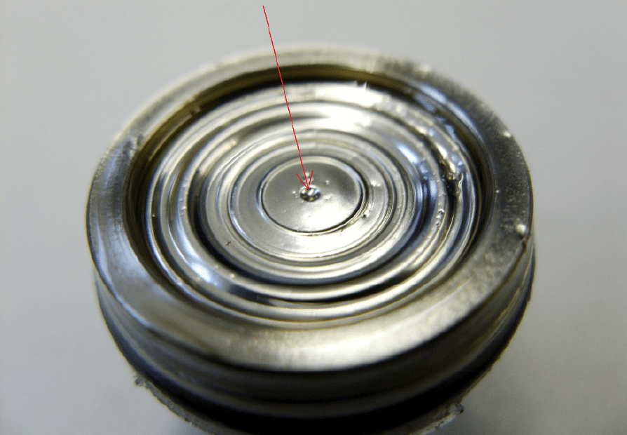
ATM.1ST/N/Ex with strain relief (left) and ballast weight (right), each screw-on.

Being an expert in customer-specific pressure transmitters, STS was able to supply the ATM.1ST/N/Ex in less than three weeks.

The features of the ATM.1ST/N/Ex in brief:

  • Pressure range: 1…250 mH2O
  • Accuracy: ≤ ± 0.1 / 0.05 % FS
  • Total error: ≤ ± 0.30 %FS (-5 … 50°C)
  • Operating temperature: -5…80 °C
  • Media temperature: -5…80 °C
  • Output signal: 4…20 mA
  • Materials: Stainless steel, titanium
  • Electronic compensation
  • Common process connections available
Pressure measurement in abrasive media using Vulkollan® membranes

Pressure measurement in abrasive media using Vulkollan® membranes

Typically, pressure sensors are available in either stainless steel or titanium finishes. In this way, all of the common test bench applications or monitoring tasks are covered. But when it comes to contact with particularly abrasive media, then additional protection is required. An added Vulkollan® membrane can often meet the requirements here.

Before turning to two specific application examples, first a few introductory words on the material itself: Vulkollan® is the trade name for a polyester-urethane rubber, a polyurethane plastic with elastic properties, as well as good chemical and mechanical resistance. This rubber-elastic material is used in different variants including foam, cellular soft plastic and also as a solid plastic. While the first two variants are predominantly used in pigging technology, the solid plastic one is processed into wheels, rollers and coatings. The operating temperature range here lies between -20 to +80 degrees Celsius.

Concrete as contact media

A market leader in the field of specialist civil engineering contacted STS in the search for a pressure sensor, which can be used without hesitation in a flowing, abrasive medium. In this particular instance, concrete was the case. The specialist engineer makes hydraulic equipment that drills holes in the ground and then fills them with concrete to form piles.

To ensure that these concrete piles have a stable structure, a continuous flow of concrete must be ensured. The concrete is filled into the hole via a pipe. After the pipe has been inserted into the hole, it can happen that concrete blocks the pipe inner, leading to an interruption of the process.

To prevent this, a pressure sensor was to be inserted into the interior of the pipe. Since the concrete is delivered through the pipe into the drilled hole by means of a pump, a blockage can be easily recognized by high pressure inside the pipe. For this task, a stainless steel pressure sensor was out of the question, since it would survive in concrete only for a short time.

To meet this challenge, STS proposed to furnish a flange sensor fitted with an additional Vulkollan® membrane. With this added protection, the sensor employed achieves a lifespan of one year at a five percent accuracy. The mechanical construction, as well as the electrical connections, are custom designs, which could be supplied within a short time.

Fill-level measurement in trimming tanks

A manufacturer of ship control systems looking for a reliable solution to water-level measurement inside trimming tanks approached STS.

Trimming tanks are used to bias the position of the center of gravity within a vessel. Cargo ships, for example, are constructed in such a way that the design waterline coincides with the actual waterline when fully loaded. But if these are put to sea without cargo, the hull lifts out of the water so much that the bow usually towers way above the water. Because of the weight of the engine, the hull sits deeper, but potentially not deep enough that the propellers are still sufficiently immersed in the water – the ship becomes unable to maneuver in this scenario. To counteract this, the trimming tanks are filled with water.

The pressure transmitters for monitoring the filling level, however, come into contact not only with salt water (where titanium housings are sufficient), but also with sand, small stones or even shells. To optimize the lifetime of the sensor, its membrane was coated with a Vulkollan® film.

Image 1: Example of a pressure transmitter with Vulkollan® foil

It is because of Vulkollan® that pressure sensors can be optimized for use within abrasive media. This does not apply, however, to explosive substances or acids. Read more about the media compatibility of peizoresistive transducers here. In addition, users must remember that this additional Vulkollan® protection adversely affects the precision of the sensor. The thermal characteristics also become more unstable.

As a result, nothing beats the comprehensive and qualified advice of experts in the search for a suitable pressure-measurement solution in abrasive media.

Pressure peaks in hydraulic systems: A risk to sensors and other equipment

Pressure peaks in hydraulic systems: A risk to sensors and other equipment

Pressure peaks occur in virtually all gas and liquid-filled pipelines. Those pressures arising in just a few milliseconds can exceed the overload pressure of the pressure transducers employed and also destroy them.

Pressure peaks, or very high pressures existing over a short timeframe, are usually noticed only when the damage has already been done. They are the result of pressure surges and also other physical phenomena (cavitation, micro-diesel effect) that occur wherever liquids or gases are transported through pipes. Pressure peaks, however, are less important among gases due to their high compressibility and thus only rarely represent a danger. In the context of water pipes, the term ‘water hammer’ is often used. With these terms, a dynamic pressure change of the liquid is ultimately implied. When, for example, a valve is quickly closed, water flow will stop instantaneously. This triggers a pressure wave, which flows through the medium against the direction of flow at the speed of sound and is then reflected back again. Within milliseconds, there is a sharp pressure increase which can cause damage to pressure sensors and other equipment (damage to pipe fittings and pipe clamps, as well as to pumps and their footings etc.). In the first line, however, it is the measuring devices that are affected, upon which we will be concentrating in the following. These damages can appear as a tiny “rupture” or a deformation (see Figures 1 and 2).

Figure 1: “Rupture” as a result of pressure spike

Figure 2: Deformations due to pressure peaks

If the pressure acting on the pressure transducer exceeds the overload pressure, then this will sustain permanent damage. There are two possible scenarios here: As paradoxical as it may sound, the complete destruction of the measuring instrument due to pressure peak is the mildest of consequences. Users, after all, do notice the damage immediately here. If the sensor is merely deformed as the result of a pressure peak, however, it will continue to operate, but deliver only inaccurate measurements. The financial consequences here are disproportionally higher than with a totally destroyed sensor.

How to prevent damage caused by pressure peaks

The golden path to preventing damage caused by pressure peaks lies in the integration of pulsation dampers or pressure chokes. Other means, such as the use of valves, would not lead to satisfactory results, because they are too slow to react to pressure peaks which actually arise in mere milliseconds.

The purpose of a choke is to dampen pressure peaks so that they no longer exceed the overload pressure of pressure transducers and then damage them. For this purpose, the choke is placed in the pressure channel in front of the sensor cell. As a result, pressure peaks will no longer reach the membrane directly and unchecked, since they must first pass through the choke itself:

Figure 3: Pressure channel with Pressure choke

Because of their very good protection from pressure peaks, the use of pressure chokes remains the best option. This variant, however, does have its pitfalls. It can lead to a blockage of the pressure channel due to calcification and deposits, especially in media with solid and suspended particles. This results in a slowing down of the measurement signal. If chokes are used in relevant applications, then regular maintenance should be carried out here.

A supplementary protection from pressure peaks can be achieved with a higher overpressure resistance, as opposed to the standard one. Whether this is advisable depends upon the particular application: If high accuracy readings are required, these can no longer be achieved in certain circumstances of very high overpressure resistance relative to the measurement range.

The diesel effect in hydraulic systems: Material damage is the outcome

The diesel effect in hydraulic systems: Material damage is the outcome

As the name suggests, the term diesel effect refers to the combustion process in a diesel engine. But it can also be observed in hydraulic systems. In addition to pressure peaks, oil aging, residues and the destruction of seals are the outcomes.

The diesel effect occurs as a consequence of cavitations. We will therefore first consider the formation conditions for cavitations in hydraulic systems before turning to the diesel effect itself.

Cavitation in hydraulic systems

Depending upon gas, temperature, liquid and pressure, hydraulic oils contain dissolved air. Cavitation is ultimately an air expulsion from the hydraulic oil. This occurs when the oil is subjected to a certain pressure or shearing motion. In practice, this occurs in suction lines, pump interior spaces, cross-sectional narrowings and, in hydraulic systems, where pulsations appear. When the moving oil mass shears, voids are formed, into which the finest of air bubbles are released.

The diesel effect

If the air bubbles resulting from cavitation, which also contain oil particles, are subjected to a high pressure, then a drastic temperature increase occurs in those bubbles. This major temperature rise leads to the diesel effect, namely combustions within the hydraulic system, and this combustion process takes place within milliseconds.

The consequences of cavitation and the diesel effect

Cavitation can have a variety of negative consequences, including material damage to pump housings and pressure relief valves, the sucking away of sealing elements such as O-rings, altered flow characteristics, reduced function of pumps and gears due to filling losses, noise, pressure surges with pressure peaks exceeding the system pressure, and the diesel effect, in the form of oil aging, combustion residues and destroyed seals.

The consequences of cavitation and the diesel effect are not always immediately apparent. They are often only noticed when it is already too late and there is a need to repair the hydraulic system. Pressure peaks as a result of cavitation and the diesel effect can also damage the pressure transmitters installed in the system by overshooting. The sudden pressure increase in the system causes the membrane of the pressure transmitter to be “shot through” (read more about this here).

In view of the serious consequences of cavitation and the diesel effect, appropriate measures must be taken to avoid these phenomena. This includes a sufficient filling in the suction chambers and low flow velocities, as well as avoiding sharp edges, deflections and pulsating pressures.

Accurate pressure measurement is crucial to developing an electric oil pump

Accurate pressure measurement is crucial to developing an electric oil pump

Driven by escalating global emissions targets, OEMs are increasingly turning to electrification to reduce fuel consumption and Greenhouse Gas emissions. A popular choice in this regard is the hybrid electric vehicle, often powered by a severely downsized engine.

The problem with these downsized engines is that power-sapping auxiliary systems severely impair drivability and performance. Fortunately these parasitic losses can be significantly reduced by replacing traditionally mechanical components with electrically driven units. Because of this, electrically powered pumps are rapidly finding their way into series production; particularly driving oil and water pumps.

Image 1: Example of an electric oil pump
Image Source: Rheinmetall Automotive

But while the benefits are obvious, electrifying, in particular the oil pump, is technically complex: Engineers, not only wish to circulate the oil at a particular flow rate and pressure, but would like to intelligently match these to the engine requirements.

In order to optimize the performance it’s important that friction and pumping losses are minimized through careful control of the oil flow into different branches of the oil circuit while ensuring the correct pressure is available at all times.

Simulation relies on accurate testbed oil pressure and flow rate information

An electrically powered oil pump is made up of three subsystems – the pump, motor and electronic controller. Therefore the primary challenge of any new application development is the efficient integration of these modules so as to reduce the overall size and weight as well as the number of components, whilst optimizing performance.

The main function of the oil pump is to deliver a specified oil flow at an optimal pressure. For this reason, its design, which is an iterative process, starts with the ‘pumping gears’. For most applications the pump is required to deliver pressures in excess of 1 to 2 bar, often going as high as 10 bar.

As in most engine developments, a combination of simulation and real world testing is used to speed up the design. 

The design loop begins with the preliminary assessment of the volumetric efficiency based on experimental results collected on similar pumps and applications. These include pump speed, oil temperature, pressure and flow rate. 

It’s important that the information used for the estimation is accurate, therefore the data collection must be carried out using highly dependable, precise measuring equipment that can deliver accurate readings under the extreme conditions encountered in and around the engine.

To ensure accuracy and repeatability it’s important that only the best quality sensors are used when measuring the pressure. Not only must these pressure sensors provide reliable readings across a wide range of pressures and temperatures, but they must also withstand vibration.

Over many years STS have developed pressure sensors that meet OEM, first tier and specialist engine designers’ requirements in engine development. 

Developing an electric oil pump that outperforms the mechanical unit 

Armed with the information gathered on the hydraulic requirements at various flow rates, delivery pressures and oil temperatures, a preliminary design of the gears is finalized. Using Matlab’s  Simulink software, the information regarding the behavior of the physical system can be rationalized into an one-dimensional code. 

At this stage it’s important to note that to generate the required flow at a specified pressure, a rotational speed should be selected that facilitates the best packaging of motor and pump without creating cavitation or noise issues: Thus a typical speed range for continuous operation is usually between 1500 and 3500 rpm. 

In the next step, several designs can be generated using LMS Imagine. Lab’s Amesim software that optimizes the design parameters – for example the number of teeth and eccentricity, while satisfying all pressure, flow and temperature boundary conditions. 

After implementing the geometrical features of the calculated hydraulics and the interim design has been finalized the total torque required to drive the pump at critical working points can be calculated as follows: 

Mtot = MH + MCL + Mμ 

Where:

  • MH is the hydraulic torque due to the generation of required pressure and flow
  • MCL is the coulombian contribution generated where there are dry or lubricated contacts between sliding parts
  • Mμ is the viscous contribution due to the fluid movement inside clearances.

Once the design is completed, engineering prototypes are constructed for real world evaluation on an engine testbed. 

Once again oil pressure, flow rate and temperature are measured at various engine and pump speeds to validate the results obtained through simulation. If the results meet the specifications the development program is finalized and the project enters the industrialization phase. 

For optimal performance and durability it’s obvious that all measurements be accurately recorded, but the weight given to information generated by the pressure sensor possibly outweighs all others – insufficient pressure at any point can lead to a catastrophic failure; while excessive pressure wastes energy and could lead to problems with the oil seals.

Subscribe To Our Newsletter

Join our mailing list to receive the latest news and updates from our team.

You have Successfully Subscribed!