Deprecated: Hook wp_smush_should_skip_parse is deprecated since version 3.16.1! Use wp_smush_should_skip_lazy_load instead. in /home/xepoxenu/www/new.stssensors.com/wp-includes/functions.php on line 6078
Testbed Archives - STS Switzerland (EN)
Deprecated: Hook wp_smush_should_skip_parse is deprecated since version 3.16.1! Use wp_smush_should_skip_lazy_load instead. in /home/xepoxenu/www/new.stssensors.com/wp-includes/functions.php on line 6078
Pressure sensors in motorsport: Where a fraction of a horsepower is decisive

Pressure sensors in motorsport: Where a fraction of a horsepower is decisive

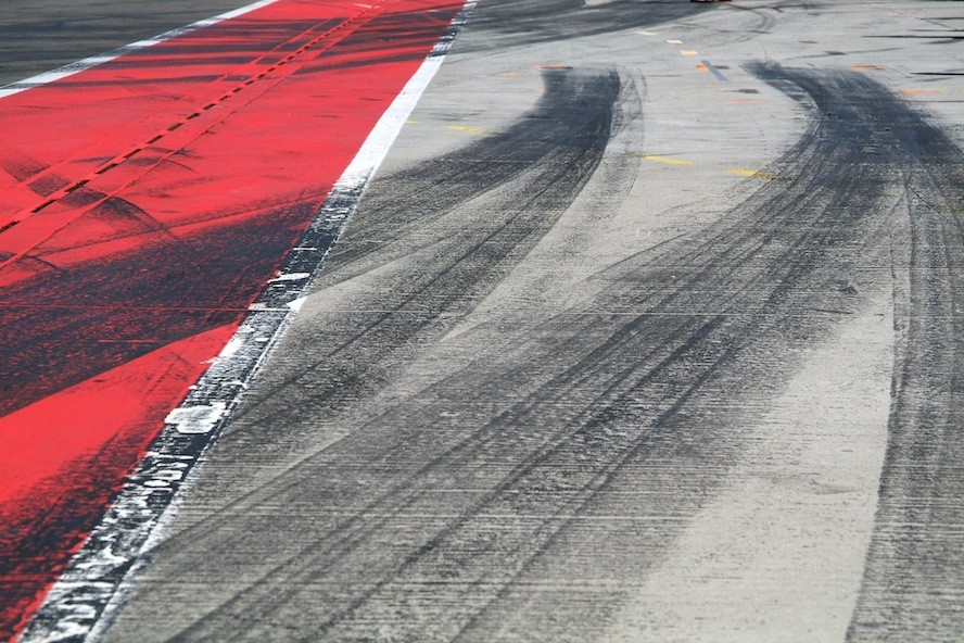
“The winner takes it all!” The world of motor racing is divided into winners and losers, with the successful driver enjoying the champagne shower. The preliminary outcome, however, takes place on the engine development test bed, with high-performance pressure sensors representing the decisive competitive advantage.

STS supplies pressure sensors to customers from the world of motorsport, including participants in Formula 1 and NASCAR. Both of these racing series, despite all their differences, have one thing in common. Every horsepower counts and embodies the decisive advantage on the track. When every tenth of a horsepower is to be wrestled from extensive analysis on engine testbeds, the end results have to be absolutely reliable down to last decimal place.

Pressure measurement technology in Formula 1 engine development

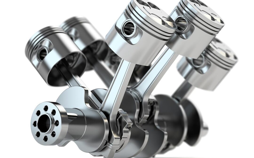
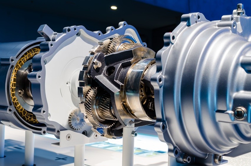
The current engine regulations in Formula 1 were introduced in 2014. V-layout engines of six cylinders, 1.6 liters displacement and a single turbocharger are driven. The rev speeds reach up to 15,000 min−1. The Kinetic Energy Recovery System (KERS), an electrical system for recovering energy under braking first introduced in 2009, has now been replaced by the Energy Recovery System (ERS). In modern Formula 1, the engines involved are thus of a hybrid type. The future of Formula 1, for this reason, has long since become the present. The perhaps most successful racing series worldwide is also a testing laboratory for the road. From disc brakes to computer diagnostics, many technologies now found in everyday road traffic have their origins in the development centers of Formula 1.

The prevailing engine regulations, which evenly delineate the parameters for all teams, make thorough research on the testbed essential to carving out the decisive advantage. Every single horsepower counts. In comparison to tests for vehicles in normal road traffic, different requirements, to some extent, are applied. Oil and water pressures are higher, as are their arising temperatures. When improved fuel economy and increased performance is the aim, then extensive testing under racing conditions is essential. Furthermore, the precision of measured results across the required temperature range is of great significance. In Formula 1, major leaps in terms of horsepower are often not the case – improvements even in the decimal regions are a reason for celebration at this elevated performance level.

In light of these challenges, a well known racing team from Formula 1 approached STS, since the hitherto employed sensor technology failed to meet their high requirements. The measuring instruments used were too big and too heavy. Even more serious, however, was the problem that additional cooling technology had to be built into the testbed, since the sensor temperatures would otherwise rapidly escalate above the maximum. Measured results under this scenario would thus be worthless.

The aim of the developers was to acquire pressure sensors that permit standardization and make additional cooling elements obsolete. The topics of weight and size also play a role, since these factors influence the performance of the speeding car.

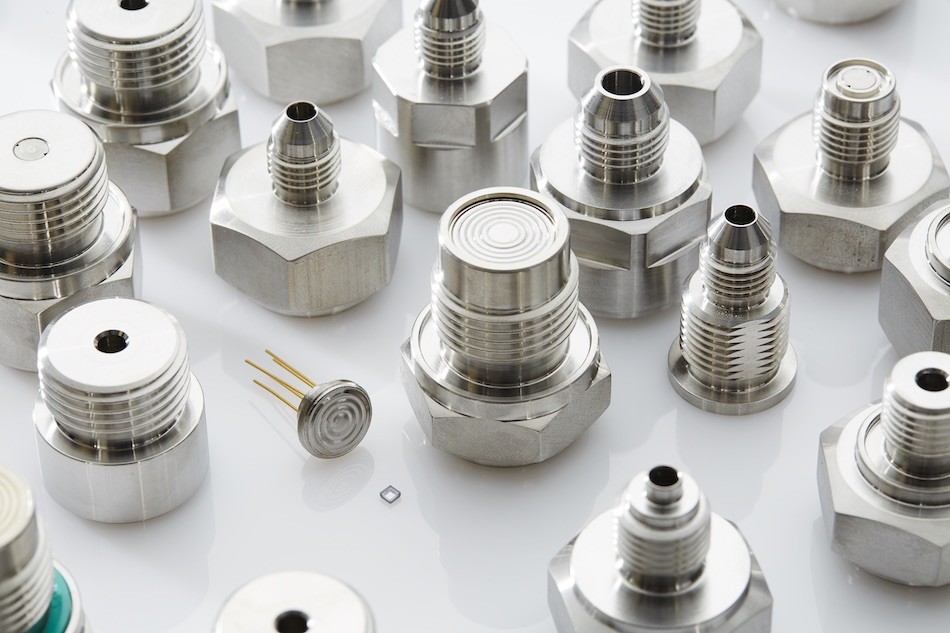
STS provided the racing team with a new sensor from the ATM series, available on the market from the fall of this year. This sensor scored not only in its desired precision across the required temperature range, but also delivered a further decisive advantage which could enduringly optimize engine development. With the previously used sensors from another manufacturer, there were malfunctions when switching to the hybrid systems employed since 2014. The results were that the testbed would shut itself down and longer term measurements were practically impossible. The ATM sensors from STS are fail-safe and thus allow for extensive testing on the road to the victory podium.

Pressure measurement technology in NASCAR engine development

Although hybrid engines are not built into NASCAR stock cars, extensive testing is still required to attain the optimum in performance. In this sport also, a well known engine manufacturer has opted for the pressure measurement technology from STS. During extensive tests, some 200 ATM.1ST pressure transmitters have been keeping an eye on oil, water, fuel and air pressures. From air pressures reaching the engine right through to improvements in oil flow, the aim is to precisely examine various factors to attain even the slightest increase in performance (involved here is ca. 900 PS). As with Formula 1, the highest of precision is required. The scope here amounts to just a tenth of a horsepower!

The manufacturer choice went to the ATM.1ST pressure transmitter, since it is largely unrivalled in its required performance characteristics.

  • The modularity of STS sensors also allows the manufacturer to connect a special pressure adapter.
  • A total error of ≤ ± 0.30 % FS permits meaningful analyses for improving engine performance.
  • Long-term stability considerably minimizes the need for calibration.
  • The pressure measuring range from 100 mbar…1,000 bar is well suited to those pressures arising during engine development.
  • Outstanding temperature compensation allows for precise results across a broad temperature range – a decisive criteria for the sharply rising temperatures during performance testing at these highest levels.

Whether in Formula 1 or NASCAR, the path to the victory podium leads through engine testbeds. In the high-performance motorsport field in particular, high-precision sensors are required for monitoring all of the important data from oil and water pressures to fuel and air pressures. Besides precision, fail-safe capability also plays an important role in being able to conduct essential long-term testing that yields reliable results.

Measuring the heartbeat of the IC engine

Measuring the heartbeat of the IC engine

As a doctor measures blood pressure to determine the health of a patient, so too, the development engineer measures crankcase pressure to gain an insight into the condition of an engine on the test-bed. Not only does an increase in pressure provide an early indication of wear, but pressure measurement is crucial in the development of modern positive crankcase ventilation systems, that need to comply with emissions regulations.

It’s important to note that the measurement of crankcase pressure is not a direct measurement of “Blowby”, which is measured as a flowrate in standard cubic meters per second.

Measuring crankcase pressure to monitor cylinder liner, piston and ring wear.

Development engines are not cheap, taken that there’s usually an intensive engineering design program behind them: Therefore, the last thing any engineer wants to see is the test literally go up in smoke. To minimize the risk, testbeds nowadays are instrumented with a myriad of sensors to monitor everything from oil pressure and ambient temperature to EGTs and of particular interest, crankcase pressure.

Crankcase pressure sensors used on testbeds are particularly interesting as, not only are they capable of measuring relatively minor variances in pressure, but they are also stable across a wide temperature range whilst withstanding submersion in hot oil: This is particularly important as the sensor is often fitted to the sump or oil filler tube where it comes into direct contact with hot engine oil.

The piston-rings-cylinder (PRC) system is subjected to extreme stresses such as high frictional and accelerative forces, as well as extreme temperatures and pressures resulting from the combustion process.

Under these conditions there will always be some form of scavenging back into the crankcase, but as component wear increases, so will the pressure inside the engine. This is the basic principle behind measuring crankcase pressure as an early indication of wear on engines running on dynamometers or testbeds.

This increase of pressure in the crankcase in forced induction CI engines can be catastrophic, as the return of oil from the compressor will often be restricted resulting in the labyrinth seal failing causing a total loss of lubrication to the bearings.

Notwithstanding the importance of monitoring the PRC system’s condition, optimizing positive crankcase ventilation through accurate measurement of internal pressure is vital in meeting emissions legislation.

Designing the PCV for a cleaner environment.

In the early 1960s, General Motors identified crankcase gasses as a source of hydrocarbon emissions. They developed the PCV valve in an effort to help curb these emissions. This was the first real emissions control device fitted to a vehicle.

Ideally, the crankcase pressure should be controlled to just above atmospheric so that there’s enough pressure to exclude dust and moisture, but not enough to force oil past seals and gaskets; or on a forced induction engine, restrict the return of oil to the sump.

The first step in the design of an effective PCV valve is to determine the actual pressure in the crankcase by using a high quality pressure sensor specifically designed to accurately measure small differentials, whilst providing accurate repeatable readings across a wide temperature range.

Armed with the data accumulated during performance and durability runs, engineers are able to determine the appropriate parameters for the PCV valve:

  • Suitable cross sectional area to facilitate sufficient vapour flow from the crankcase
  • Correct operating pressure parameters to ensure unrestricted oil return on turbocharged engines, whilst retaining positive internal pressure.

Finally the prototype valve is evaluated on a testbed, again with crankcase pressure sensors fitted, to confirm performance and durability, as well as emissions compliance.

This development can span weeks and account for a sizeable chunk of the development bill, so the last thing a manufacturer would want is the failure of a vital sensor; which would require a partial, or even complete retest. That’s why OEMs only use high quality pressure transmitter, such as those produced by the pressure transmitter and transducer manufacturer STS.

Accurate pressure measurement is critical to safe, cost-effective, motor vehicle development

Accurate pressure measurement is critical to safe, cost-effective, motor vehicle development

The principle of hydraulic power to carry out work has been around since ancient Egyptian times, but as systems have evolved, so too have the tools required to design and develop these sophisticated, often critical circuits.

From the earliest manometer invented by Evangelista Torricelli in the 1600’s to the mechanical Bourdon gauge and finally today, the piezoresistive pressure transducer, developers have always sought the best equipment to measure pressures and optimize the design. And in recent times automotive engineers, in particular, have come to rely on these high-quality, accurate pressure sensors when carrying out vehicle testing and development.

These current pressure transducers are typically capable of recording full-scale deflections from about 350 mbar to 700 bar under sustained temperatures ranging from -40OC to 150°C; and best of all, quality sensors such as those produced by STS, are capable of a hysteresis and repeatability of typically around 0.001%!

Image 1: High precision pressure transmitter ATM.1ST with accuracy of up to 0.05% FS

High-quality pressure sensors are used in the development of key automotive systems.

This level of repeatability is critical in the design and development of cooling and fuel delivery systems, amongst others. During development, designers rely on stable pressure measuring equipment to accurately record information so that the effect of even the smallest of design changes can be documented without concerns that the sensor is incapable of repeatable results.

In a recent redesign of an engine cooling system to take advantage of the reduced parasitic losses made possible through electrification, the engineering team at a luxury OEM was initially faced with a pressure drop across the pump of around 250kPa. Before a redesign of the new electric pump was possible, accurate pressure measurements had to be recorded allowing engineers the opportunity to identify the problem. After studying the results logged by the array of pressure sensors the design was modified, reducing the drop to less than 100kPa and cutting the parasitic losses by 500W.

And although electrification and electronic controls are playing increasingly significant roles in vehicle systems, hydraulic pressure is still relied upon to guarantee smooth operation of many critical circuits.

By way of example, during the development of an automatic transmission, port line pressures have to be measured in real time and then compared to design norms to confirm that design parameters are being met. At the same time, shift times and quality are measured and subjectively evaluated to ensure drivability and performance meet customer requirements.

Notwithstanding the value of high-quality pressure sensors in recording valuable data during testing and development, in industrializing future technologies these tools can also significantly reduce design costs.

Pressure sensors make sure future technologies measure up to expectations.

In an attempt to improve the performance of severely downsized engines, manufacturers are taking advantage of the additional power 48V electrification offers, by replacing the turbocharger with an electrical supercharger.

Being a maturing technology, not much research and testing data are available to engineers wishing to optimize eCharge superchargers. Although fluid dynamics and electrical engineering provide a sound platform from which to build, it’s still vital that theories are validated under real-world test conditions.

To achieve this, manifold pressures must be mapped to optimize engine performance while maximizing the energy recovered from the exhaust gas. For this, extremely accurate pressure sensors that provide precise readings over a wide range of manifold boost pressures and temperatures are required. These sensors must also be resistant to vibration and chemical degradation.

And while manufacturers around the world continue to carry out research into electric vehicles, several groups are considering ways to harness hydrogen to generate electricity instead of relying on storage batteries.

Hydrogen fuel cells employing proton exchange membranes, also known as polymer electrolyte membrane (PEM) fuel cells (PEMFC), have already seen limited series production in vehicles such as Toyota’s Mirai.

Although small PEM fuel cells commonly operate at normal air pressure, higher powered fuel cells, of 10kW or more, usually run at elevated pressures. As with conventional Internal Combustion Engines, the purpose of increasing the pressure in a fuel stack is to increase the specific power by extracting more power out of the same size cell.

Typically the PEM fuel cell operates at pressures ranging from near atmospheric to about 3Bar, and at temperatures between 50 and 90°C. While higher power densities made possible by increasing the operating pressure, the net system efficiency may be lower due to the power needed to compress the air; hence the importance of balancing the pressure to the requirements of the particular fuel cell.

As with ICE boost pressures, this can only be done by taking accurate pressure measurements using high-quality pressure sensors. These measurements are then compared to the fuel stack outputs to minimize the parasitic losses while optimizing the gains in electrical output.

So, irrespective of the course the automotive industry chooses for future technologies, accurate pressure sensors will remain key to the development of safe and efficient vehicles.

How to select the right pressure sensor?

How to select the right pressure sensor?

Extensive testing is essential in the development of new technology. To achieve reliable results, measurement instruments are required which precisely meet the requirements. We show you which factors play a role here.

Pressure range

An initial indicator in the search for a suitable measurement technology is the pressure range to be measured and whether a measurement of the relative or absolute pressure is anticipated.

Depending upon application, special features have to be considered. Particularly in test and measurement applications, individual measurement ranges are required which standard sensors with ISO pressure ranges cannot deliver. In this case, sensors are needed which display the appropriate pressure range and thus attain the desired precision.

Precision

In engine development for racing cars, the smallest of measured readings are the deciders between victory and defeat on the track. In this case, the utmost in precision is demanded and in specific applications developers will opt for a sensor with ±0.05% FS.

Within this question of precision, the factors of necessity and cost are balanced against one another. The pressure range to be measured is usually a good decision-making aid. If this were extremely broad, then no exceptional precision would be necessary. Those who nevertheless decide for the most precisely available sensors should be aware that this precision comes at a price.

Temperature

The temperature factor in some cases is difficult to determine. Developers are often not exactly aware over which temperature ranges the pressure sensor employed is to deliver its service. Many pressure transmitters from STS , for example, are optimized for operating temperatures from -25°C to 100°C. In this way, the common areas of application are all covered. In principle, all sensors can be optimized and ordered to a special temperature range so that even at temperatures of -40°C or 150°C accurate results can be attained.

Process interfacing

The subject of process interfacing can quickly become an exclusion criterion for developers, since many companies use standardized connections. Even the location where the sensor is to be mounted can be an important factor here.

There are a multitude of optional electrical connections, whether it be M12, DIN, MIL or others, which should also be offered by manufacturers in a variety of lengths and materials.

STS itself provides a broad range of connectors. A multitude of connection options are possible due to the modular construction principle of these measurement instruments.

Output signal

Equally decisive is the question of whether the measured pressure is to be carried as an analog signal or over a digital interface such as Modbus. With an analog signal transmission, the pressure is converted into an analog signal that still needs to be measured. In a digital signal transfer, the value of the measured pressure is directly expressed across an interface.

Space requirements

In various applications, only a little space is available for the mounting of pressure sensors. For this reason, the size of the sensor combined with the available process interfaces can become an important selection criterion. The form of pressure measurement also plays a role here. Piezoresistive pressure sensors are particularly suited to miniaturization. For this reason, STS can offer sensors of only a few millimeters in diameter.

Materials

Where will the sensor be deployed? Which ambient conditions will it encounter? Will it come into contact with steam, gasoline or particular gases? The housing material determines which media the sensor will be exposed to. For applications on the test bench, stainless steel housings are mainly used. Upon contact with saltwater, the material selection shifts to titanium.

A major influence upon the appropriate sensor is also played by the sealant material. The sealing material remains dependent upon the fluid used in the pressure system. Temperatures to be anticipated must also be expressly included during these considerations.

Certifications

When using in particularly dangerous applications, such as the possibility of explosion, certain certifications are essential which supply information about safe operation of the instruments. Within the STS portfolio, there are sensors like the ATM.ECO/IS, which carries the FM, Fmc, IECEx, ATEX certification, whose use is authorized in explosive areas

Delivery period

Long delivery periods can delay prototype testing and ultimately jeopardize product introductions. It should thus be established in advance whether the required sensors are available or what delivery period is to be anticipated for custom production.

Click on the graphic to download it

The right pressure sensor – Summary

Sensors do not necessarily meet all of the required specifications. In some cases, the required sensor from one manufacturer is not available in the company’s standardized connection option. Considerable additional costs could arise in this case. Delivery periods could also be correspondingly delayed.

To make the choice of the right sensor as easy as possible for customers, our pressure measurement instruments are based on a modular principle. This means that all of our pressure sensors can be calibrated to the required temperature range. Our products are also exceptionally flexible in terms of process interfacing, sealant materials and pressure measurement ranges. Due to the modular construction of our measurement technology, it is possible to deliver pressure sensors to the exact required specifications within the shortest of times.

Subscribe To Our Newsletter

Join our mailing list to receive the latest news and updates from our team.

You have Successfully Subscribed!