Deprecated: Hook wp_smush_should_skip_parse is deprecated since version 3.16.1! Use wp_smush_should_skip_lazy_load instead. in /home/xepoxenu/www/new.stssensors.com/wp-includes/functions.php on line 6078
Tire Manufacturing Archives - STS Switzerland (EN)
Deprecated: Hook wp_smush_should_skip_parse is deprecated since version 3.16.1! Use wp_smush_should_skip_lazy_load instead. in /home/xepoxenu/www/new.stssensors.com/wp-includes/functions.php on line 6078
Pressure measurement technology in tire manufacturing

Pressure measurement technology in tire manufacturing

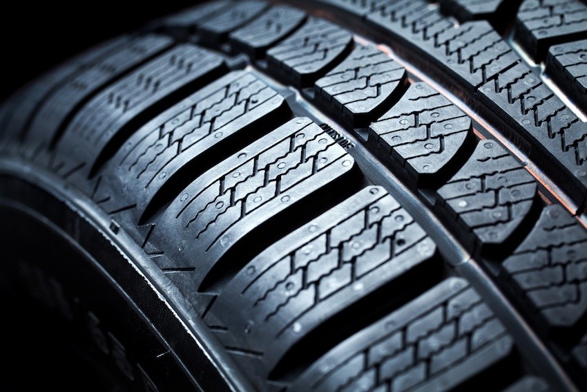
Every year, over one billion tires are manufactured worldwide. This sector thus counts among the biggest consumers of natural rubber. To give this natural material its correct shape and durability, high pressures and temperatures are necessary. No problem at all with the correct measurement technology.

Those believing that tire manufacture is a simple process, where the raw material is merely brought into a round form, are mistaken. In modern tire production, numerous individual components come together, which provide for both drive comfort and safety.

Tire manufacture – The first steps towards blanks

The manufacture of the raw material differs from one manufacturer to another and even from one tire type to another. Over forty different raw materials can be used here, including natural rubber, but also carbon black, sulfur and others. The various materials are kneaded together under extremely high temperatures. This mix is then stretched in length and ready for further processing upon cooling.

Using this mixture, the individual layers of the tire are produced. Other materials also come into use here, such as the rubber covered steel mesh in the belt, which stabilizes the tire and provides for increased cornering force. Further components of a tire include the carcass, bead, tread, sidewall, filler and inner liner.

The individual layers of a tire are brought together in a tire-building machine. These versions are termed blanks or “green tires.”

From blank to finished tire

In the next step, the blanks are inserted into the vulcanization press.  At this point, the individual tire components are vulcanized together and the material then attains its required elastic consistency. To achieve vulcanization, the blank is “baked” in the press at a determined pressure and at high temperature.

During this process, the rubber bladder is inflated from within the inside of the press and forced outwards under pressure into the mold. This is how the tire profile is created. Temperatures reach up to 180°C here and pressures of over 24 bar can arise. This blowing pressure is monitored by various prestigious tire manufacturers using the ATM Sensor made by STS.

Vulcanization only with high-performance pressure transducers

With heat, steam and high pressures, harsh conditions are at play in tire manufacture. A pressure transmitter is thus required which can monitor, also at high temperatures, the pressures arising and can withstand the demands over a longer time. The transmitters of the ATM series are predestined in this scenario. Their high precision, reliability and outstanding long-term stability, as well as their compact and resilient design, provide for efficiency. In particular, their outstanding qualities during test and burst pressures prevent costly downtime. Furthermore, these pressure transmitters can easily be calibrated anew on-site.

MaP sensors are key to clean engine performance

MaP sensors are key to clean engine performance

In the face of ever tightening Global emissions regulations the motor industry has rapidly adopted clean technologies to reduce harmful Greenhouse gases. Critical to the operation of modern clean-burn engines is the precise control of air-fuel ratios (A/F) to stoichiometric values to attain high catalytic converter efficiency and minimize tailpipe emissions.

In order to optimise the A/F ratio under transient conditions manufacturers employ both closed and open loop systems:

  • A closed-loop system is one in which a signal proportional to the A/F is generated by an exhaust gas oxygen sensor (EGO), also known as a Lambda sensor, located in the exhaust stream.
  • An open-loop, or feedforward system controls injector fuel flow through signals received from an air flow meter.

In both cases signals are fed back through a digital PI controller to regulate the fuel injection pulse width. However these systems have two significant drawbacks:

  • Due to the relatively long delay inherent in the induction-compression-power-exhaust cycle of the engine the feedback, or closed-loop portion of the A/F control system, is only fully effective under steady-state operating conditions.
  • A reliable EGO sensor signal is only available after the sensor has warmed up, and thus closed-loop A/F control is not possible immediately upon starting the engine.

Hence, under transient and cold start conditions, the feed forward portion of the A/F controller is particularly important.

To optimise the A/F under all conditions modern engines are commonly fitted with a Manifold air Pressure (MaP) sensor to measure air pressure in the intake manifold.

The MaP sensor knows just what the engine needs

The MaP sensor continually measures the air pressure, and sends this information to the engine ECU, which inserts the data into a table which is used to control the Injector Pulse Width and Ignition Timing. These pressure readings are relayed to the ECU as output voltage signals.

During the development phase it is critical that the pressures measured in the manifold are accurate. Series production MaP sensors, whilst excellent at feeding signals to the ECU, often have wider tolerances than deemed acceptable for development: Therefore high quality pressure transmitters, such as those produced by STS, are commonly fitted in tandem to the series MaP sensors during the development phase. The readings obtained from these sensors are used to measure any deviations or errors when recording manifold pressures at various throttle openings.

The process is quite complex and requires that output voltages are measured at hundreds of throttle opening points, in order for the engine ECU to create an effective map of the engine’s requirements.

Using the Map sensor to teach the engine ECU

During the development phase, using a calibrated MaP sensor, the manifold pressure is measured at small throttle opening increments and the output voltages recorded against each setting.

At idle, with the throttle partially open, this pressure is measured at around 1/3 of atmospheric pressure, or 0.338Bar in a normally aspirated engine. Since the output voltage of the map sensor is proportional to the increase in pressure, the output voltage at idle will be approximately 5/3 = 1.67V where the nominal full scale output is 5V.

However, in practice, the full scale output of a production map sensor can vary and is usually less than 5V. This is because ofvariations among sensor manufacturers, with the result that a typical full scale voltage is around 4.6V. Because of these variances, during normal operation the map sensor reading will vary between about 1.5 V and 4.5V, with the exception of the vacuum created on the overrun where output voltages of less than 1V can be recorded.

Furthermore, since barometric pressure has a significant impact on the fuel mixture the ECU must also understand what the barometric pressure is. To accomplish this ambient pressure measurements are typically recorded just before the engine is started, just after it is turned off or both.

These measurements are usedto set a baseline condition which corrects the manifold pressure for weather and elevation conditions. In practice this is achieved using ignition-on and engine-off signals. This way, the same sensor that controls the engine while it is running is used for the barometric measurement when the engine is off.

Forced induction turns up the pressure on MaP sensors

When a naturally aspirated engine is converted to forced induction through the addition of a turbo or supercharger, the manifold pressure range has to be extended to include the boost region as well as the vacuum region. In order to cover the full pressure range, a map sensor must be used that covers at least 1.5 bar of pressure or a range that matches the engine design parameters.

Should boost pressures exceed 1.5 bar it’s important that, in order to maintain a full scale reading, a decreasing offset is added to the reading as pressure increases. This has practical importance because in map sensor based engine management systems, it is easy to hit-fuel cut or generate a fault in the ECU if the nominal full scale reading is surpassed. That is why a decreasing offset is mapped when a 2 bar sensor is used to read pressures above the nominal full scale pressure.

Sourcing MaP sensors to effectively meet these wide ranging requirements is not always easy. However, with the MaP sensor playing a crucial role in the effective management of the combustion process it’s important that, in order to accurately record manifold pressures during development, a precisely calibrated high quality MaP sensor is used. And with manufacturers under pressure to further reduce emissions and improve performance, application engineers will continue to demand improvements in the accuracy of the sensors used for development.

Subscribe To Our Newsletter

Join our mailing list to receive the latest news and updates from our team.

You have Successfully Subscribed!