Mapping boost pressure on downsized turbo engines is the key to success

Mapping boost pressure on downsized turbo engines is the key to success

To meet ever tightening emissions legislation across the world OEMs are turning to downsized Spark Ignition engines. While these smaller engines consume less fuel and produce significantly lower emissions they require forced induction to deliver the performance drivers have come to expect from modern passenger vehicles.

The driveability of these downsized turbo engines must at least equal the performance of their naturally aspirated equivalents. This requires full boost pressure at low engine speeds without running out of steam at high speed, which can only be achieved with a sophisticated boost pressure control system.

The main problem with these forced induction spark ignition engines is the precise control of the air-fuel ratio near stoichiometric values at different boost pressures. At low speeds, these engines are prone to knock under medium to high loads.

Modern pressure control systems

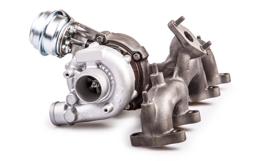
Controlling the turbine-side bypass is the simplest form of boost pressure control.

Once a specific boost pressure is achieved, part of the exhaust gas flow is redirected around the turbine via a bypass. A spring-loaded diaphragm usually operates the wastegate which opens or closes the bypass in response to the boost pressure.

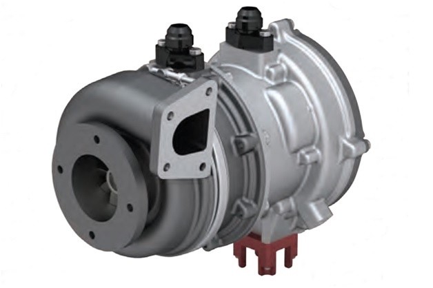
In recent times manufacturers have turned to variable turbine geometry to regulate boost pressure. This variable geometry allows the turbine flow cross-section to be varied to match the engine operating parameters.

At low engine speeds, the flow cross-section is reduced by closing the guide vanes. The boost pressure and hence the engine torque increases as a result of the higher pressure drop between turbine inlet and outlet. During acceleration from low speeds the vanes open and adapt to the corresponding engine requirements.

By regulating the turbine flow cross-section for each operating point the exhaust gas energy can be optimised, and as a result the efficiency of the turbocharger and therefore that of the engine is higher than that achieved with bypass control.

Today, electronic boost pressure regulation systems are increasingly used in modern Spark Ignition petrol engines. When compared with purely pneumatic control, which can only function as a full-load pressure limiter, a flexible boost pressure control allows an optimal part-load boost pressure setting.

The operation of the flap, or vanes, is subjected to a modulated control pressure instead of full boost pressure, using various parameters such as charge temperature, ignition timing advance and fuel quality.

Simulation reduces time to production and development costs

Faced with a plethora of complex variables, manufacturers have turned to simulation during the design and test phase.

A significant hurdle to overcome with downsized turbocharged engines is the narrow range within which the centrifugal compressor operates stably at high boost pressures.

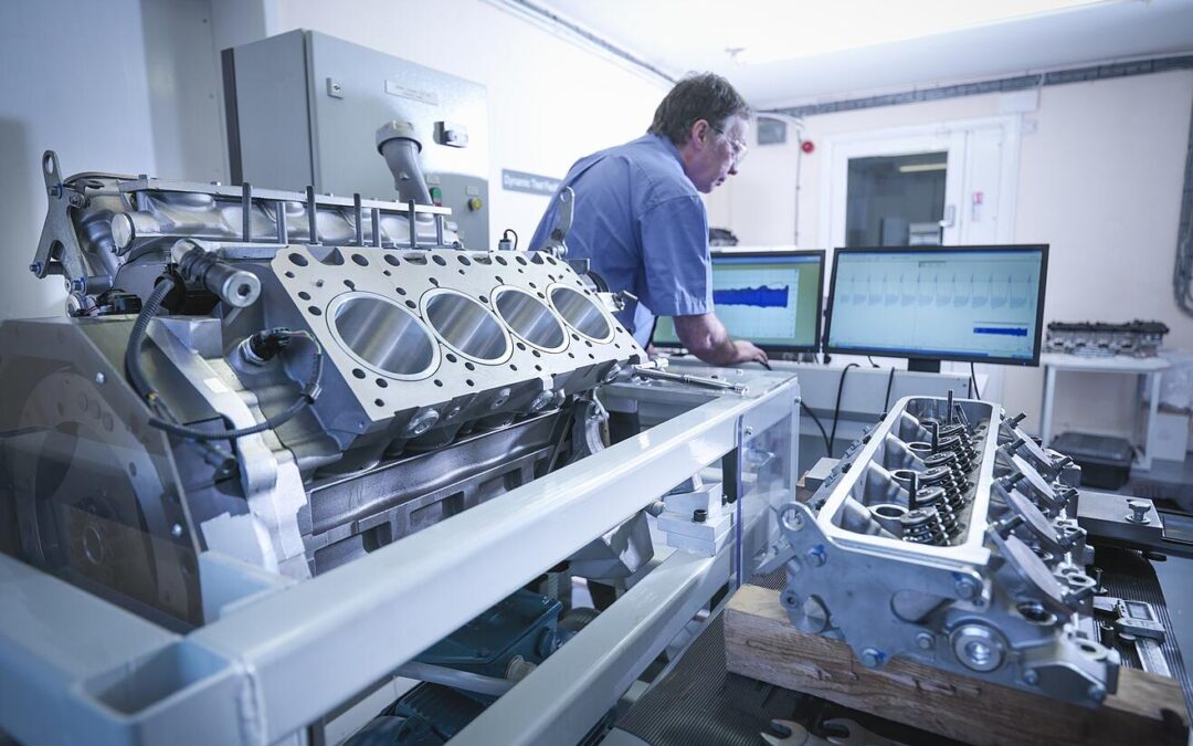
The only way to build an effective simulation model is through extensive real world testing. This testing is mostly carried out on engine dynamometers in climatic chambers.

During wide open, and part throttle, runs the following pressure information is recorded:

  • Intake manifold pressure
  • Boost pressure
  • Barometric pressure

Of course this is all integrated with engine temperatures (Coolant and oil) to gain a picture of engine performance over the full engine speed range.

During this testing it’s important that engineers note any abnormalities in performance, as events such as exhaust pulses at specific engine speed can set up standing waves which can excite the impeller at a critical frequency which will reduce the life of the turbo, or even lead to catastrophic failure.

Therefore the measurement of pressure performance maps of both compressor and turbine is vital for the creation of an accurate extrapolation model for implementation during simulation.

A well-developed simulation tool can save the OEM time and money in dynamometer and road tests, but can only be developed once the pressure maps have been completed.

The turbocharger succumbs to the pressures of energy conservation

The turbocharger succumbs to the pressures of energy conservation

For many years turbochargers were only found on expensive sports cars and diesel powered engines, but emissions regulations changed the way the world viewed forced induction. Although at the core was still the quest to improve performance, now manufacturers were looking at restoring performance and driveability to downsized fuel-sippingengines. So in the 21stCentury, almost everything from the little 999 cm3 Ford Ecoboost to the latest Ferrari’s all gained shiny new turbo technology.

But almost as soon as the tech came into its own it seems set to become redundant, upstaged by the new eCharger. Already Audi’s fitted this to the series production SQ7 and will be rolling out the technology to future production vehicles as 48 Volt electrification gains traction.

The key advantage to the electrically driven supercharger is that, as with turbochargers, there are no parasitic losses; but unlike most turbo’s there’s no turbo lag either and no need for a wastegate. The powerful electric motor can spool up the impeller to 70,000 rpm in less than a second, which eliminates turbo lag.

This naturally improves driveability and reduces consumption and emissions by between 7 and 20 percent when the device is used on a vehicle equipped with regenerative braking, which captures the car’s kinetic energy and turns it into electricity.

Pressure is key to unlocking the eCharger’s performance

Electronically controlled, the eCharger can be mapped to optimize engine performance while maximizing the energy recovered from the exhaust gas, but in order to achieve this Utopia, engineers need to create a map of the boost the engine requires by measuring manifold pressures at various engine loads and speeds. This can only be done with the aid of top quality pressure sensors.

As with any super/ turbo-charger, it’s important that the unit is matched to the engine’s requirements: Failing to do this, will either starve the engine or result in unnecessary electrical power consumption.

Being a maturing technology, not much research and testing data is available to engineers wishing to explore the boundaries of eCharge superchargers. Although fluid dynamics and electrical engineering can provide good foundations from which to build, it’s still vital that theories are validated under real-world test conditions.

In order to qualify the performance, once the baseline eCharger has been selected, the vehicle is equipped with extremely accurate pressure sensors that are readily calibrated and provide precise readings over a wide range of manifold boost pressures and temperatures. These sensors must also be resistant to vibration and chemical degradation.

Both on the engine dynamometer as well as road testing, throttle position/ engine speed/ Manifold air Pressure and temperatures are continuously recorded to ascertain the interrelationship of these key inputs.

From this information, engineers are able to verify that the correct eCharger configuration has been selected whilst at the same time ensuring that the closed loop engine management controls are able to correctly respond to the key variables.

The result of getting this right delivers a vehicle, such as the SQ7, which has stunning performance, drive ability and fuel consumption whilst still meeting future global emissions regulations.

Manufacturers are feeling the pressure

Manufacturers are feeling the pressure

With emissions regulations set to ratchet up a notch in China, Europe and North America, manufacturers are hard-pressed to optimize every engine component and function to cost effectively meet the new demands.

Although engines that are under development have always been tested to ensure they meet the most stringent quality requirements in terms of materials, emissions and efficiency, there’s a renewed focus on detailed development to unlock performance that may have previously been overlooked.

In order to do this, every time an engine is run on a test bench all the variables influencing emissions and performance have to be monitored and measured to understand their individual performance as well as how they function as part of the overall system.

This requires highly dependable, precise measuring equipment that delivers accurate readings under the extreme conditions encountered in and around the engine. Sensors of this quality and accuracy are manufactured by only a handful of suppliers around the world, which are standing out for the ability to customize quality pressure sensors to the customer’s requirements.

Pressure sensors are key to eliminating inefficiencies

STS have developed pressure sensors that meet OEM, first tier and specialist engine designers’ requirements in engine development. Using these sensors customers carry out development and design work that focuses primarily on reducing exhaust emissions and achieving a high power density, low fuel consumption, long service life and maximum reliability.

Because an engine’s efficiency depends largely on airflow and charge density into the combustion chamber and how the exhaust gases are either used to enhance the engine’s torque, by way of a turbocharger, or are able to be discharged efficiently, accurately mapping key pressure regions is critical. These pressures are often of the order of millibars, requiring extremely accurate and highly dynamic measurement.

Furthermore to obtain a reliable analysis of pressure distribution within the inlet manifold, it is important to take inlet pressure measurements as close as possible to each inlet valve. This is to accommodate the varying geometry of the manifold which often results in each cylinder being supplied with a different amount of air, which negatively impacts both performance and emissions.

When determining the performance of the exhaust system, pressure measurement becomes quite complex, as not only does the performance of the exhaust rely on pressure but also the interaction of the exhaust-gas pulses due to the engine’s firing order. STS pressure sensors are capable of measuring these processes on both the inlet and outlet sides with a high level of accuracy.

Robust sensors must remain accurate in a hostile environment

In the test environment the sensors must be resistant to the chemicals and oils associated with engines, and be able to accurately measure pressures in extreme temperatures. Moreover, the sensors need to operate reliably and not be affected by vibration or voltage fluctuations.

STS’ range of sensors also allows customers to take measurements in critical systems such as oil, fuel and water pumps, injector lines, intercoolers, and heat exchangers. All of which are vital in optimizing engine efficiency.

So although customers and regulators are increasing the demands for cleaner and better performing engines, OEMs and suppliers are well equipped to stretch the envelope and even exceed expectations.

Subscribe To Our Newsletter

Join our mailing list to receive the latest news and updates from our team.

You have Successfully Subscribed!