Strain gauges in pressure measurement technology
Strain gauges are measuring devices that change their electrical resistance through mechanical deformation. They are used in a variety of measuring instruments, which, besides scales and load cells, also includes pressure sensors.
Pressure sensors rely on several physical variables, including inductance, capacitance or piezoelectricity. The most common physical property by which pressure transmitters operate, however, is the electrical resistance that can be observed in the metallic deformation, or piezoresistive effect, of semiconductor strain gauges. The pressure is determined by a mechanical deformation, where strain gauges are attached to an elastic carrier. It is important here that the strain gauges can follow the movements of this carrier. If a pressure acts on the carrier, the deformation arising brings about a change in cross-section of the conductor tracks, which in turn causes a shift in the electrical resistance. It is ultimately this change in electrical resistance that a pressure transducer records and from which the pressure can then be determined.

Figure 1: Strain gauges deform under pressure
The deformation acting upon the conductor will thus cause it to change in length (Δl). Since the volume remains the same, it is the cross-section and thus the resistance R that changes:
ΔR/R = k • Δl/l
The change in resistance (ΔR) is proportional to the change in length (Δl), and the proportionality factor (k) will depend on both the geometry and the material properties. While ‘k’ will be 2 for metallic conductors, it can also be very high in semiconductors. Because of these relatively high ‘k-factors’ for semiconductors, these are more sensitive and can therefore measure even the slightest of pressure changes. Temperature dependency, however, also increases as a result of this.
The change in resistance in metallic strain gauges results from dimensional changes (geometry). In semiconductor strain gauges, however, the change is due to alterations in the crystal structure (piezoresistive effect).
The evaluation of the resistance change triggered by a pressure-induced deformation then takes place via a bridge circuit. For this purpose, the strain gauges are connected up to form a Wheatstone bridge (Figure 2). Two of the strain gauges are placed in a radial direction and two in a tangential one. It is thus so that two become stretched and two become compressed under deformation. In order for temperature effects to be compensated and for the signal to be as linear as possible, it is important that the strain gauges have the exact same resistances and are arranged in an exact geometry.

Figure 2: Bridge circuit
Metallic strain gauges
Among metallic strain gauges, we must differentiate between the foil and thin-film varieties.
Foil strain gauges consist of rolled foil, only a few microns thick. Constantan is normally used as the material here, but Karma and Modco can also be employed, especially if a larger temperature range is needed or the temperatures are below -150 °C. Constantan has a very low ‘k-factor’ of 2.05 and is therefore not very sensitive. Considering this, the material displays a lowered temperature dependency, which is also why it is most often used in foil strain gauges.
Foil strain gauges are more likely to be used in load cells. Often they are not sensitive enough to be pressure transducers, since values of less than one bar cannot be recorded with them. Their temperature range is also relatively limited, and, depending on the version, temperatures of even 80 °C should not be exceeded.
Thin-film strain gauges are produced by the so-called thin-film technique, by, for example, vapor deposition or sputter coating. The manufacturing process is more complex here and also more expensive than for foil gauges. On the other hand, however, a temperature range of 170 °C is possible, with their long-term stability also being very good.
Metallic thin-film strain gauges provide for stable over the longer term, but also quite expensive, measuring instruments. It holds true that the lower the pressures to be detected are, the higher the manufacturing cost will be. Low pressures of less than 6 bar can only be detected at a poor accuracy.
Semiconductor strain gauges
Semiconductor strain gauges operate by the piezoresistive effect. The material used in most cases is silicon. Semiconductor strain gauges tend to be more sensitive than the metallic variety. They are also usually separated from the medium by a separation membrane, with the pressure being passed on via a transfer fluid.

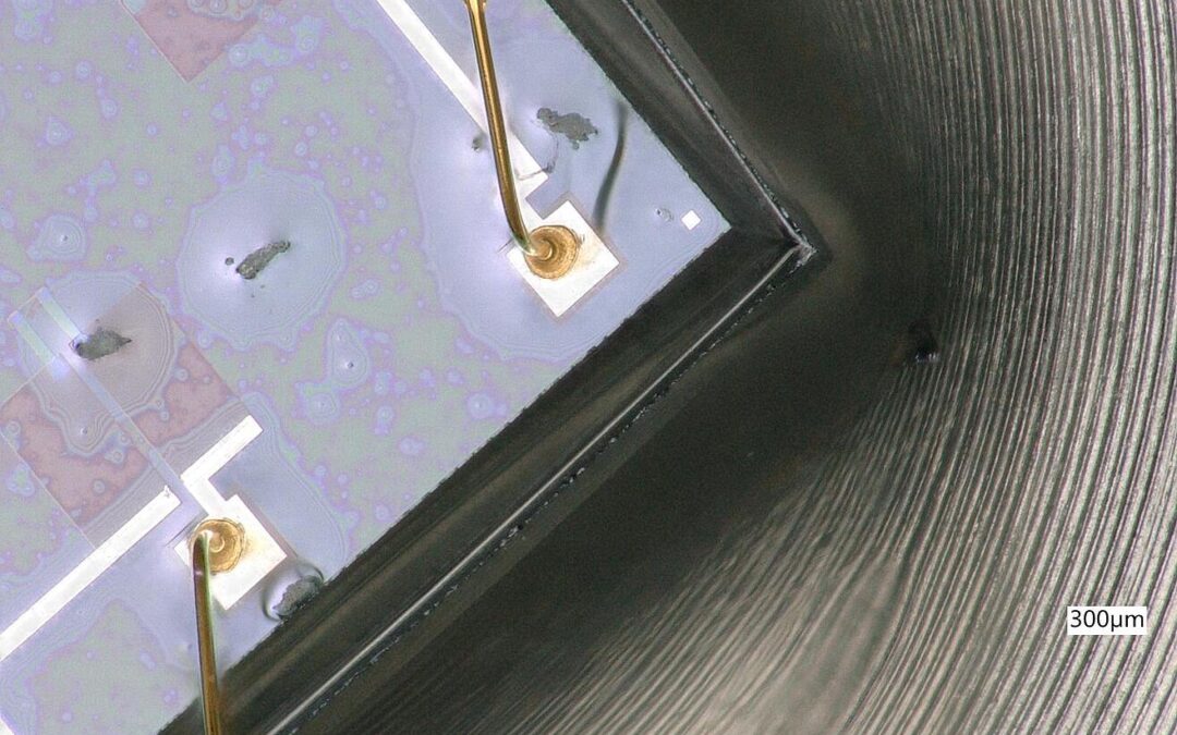
Figure 3: Piezoresistive measuring device
In semiconductor materials, the piezoresistive effect is about fifty times more pronounced than with metallic strain gauges. The semiconductor strain gauges are either glued to a carrier or directly sputter-coated onto it. The latter enables an intense bonding and assures freedom from hysteresis, as well as a resistance to aging and temperature stability. Although the piezoresistive effect is not exclusive to the semiconductor strain gauge, the term “piezoresistive pressure sensor” has come to be used for instruments where the elastic structure deforming under pressure and the resistors are all integrated into one chip. Piezoresistive pressure transducers can be made small in size and (apart from the membrane) without any moving parts. Their production is based on normal semiconductor fabrication methods. At the same time, there is the possibility of integrating the resistors with the elastic membrane deforming under pressure all into one chip and thus produce a full pressure measurement cell in the size of just one chip.
Piezo thin-film strain gauges are attached to a silicon carrier and separated from the carrier by an insulating layer. This increases the manufacturing requirement and thus also the price, but temperature ranges from -30 °C to 200 °C are possible here. Thanks to the highly elastic properties of silicon, only a low hysteresis can be expected with these. It is the high ‘k-factor’ that achieves the high sensitivity, making piezoresistive pressure transmitters the first choice for the smallest of pressure ranges on the mbar scale. In addition, devices of tiny dimension can be produced, which has a positive effect on the scope of potential applications. Also, the long-term stability and EMC compatibility is very good, with the latter, of course, depending upon carrier material. Temperature compensation, however, requires a little more effort, but even this challenge can also be overcome quite easily. You can read more about temperature compensation here.
Thick-film strain gauges are printed onto ceramic or metallic membranes. With a thickness of 20 microns, they are up to 1,000 times thicker than thin-film strain gauges. Because of their low production requirements, these are cheaper in price, but not very stable longer term due to the aging of their thick film.
Summary: The type of strain gauge used has a major influence on the measuring instrument. Factors such as price, accuracy and long-term stability play an important role in choosing the right pressure transmitter. In our experience, pressure transmitters with piezo thin-film strain gauges have proven to be the most efficient, because, thanks to their sensitivity, they can record wide pressure ranges at high accuracy, whilst also exhibiting good long-term stability.