Ideally, pressure transmitters are installed directly within the process to be monitored. If this is not possible, the process medium to be monitored will then decide upon the positioning of those sensors.
There are various reasons why pressure transmitters cannot be mounted directly within the process:
- there is not enough space for installation within the application
- the pressure sensors are to be subsequently installed
- a direct contact between process medium and measuring sensors is undesired (e.g. due to excessive temperatures)
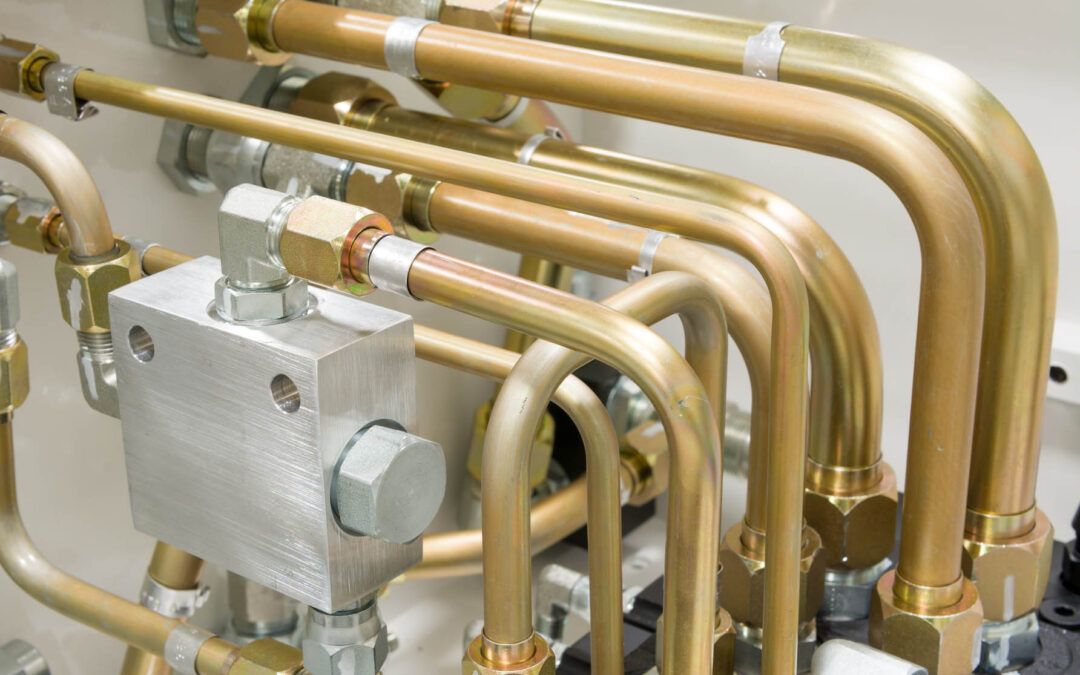
If the pressure sensor cannot be mounted directly in the process, the connection between process and measuring instrument is established via a bypass line (also termed differential pressure line or branch line). This connecting line is filled with gas or liquid, depending on the type of application. As a rule, there will be a shut-off valve both on the bypass line near the process and also near the pressure transmitter. This allows the measuring device (or parts thereof) to be dismantled or modified without interrupting the actual process.
This is particularly helpful when the pressure transmitter is subject to maintenance work, such as calibrations. The measured medium remains in the bypass line due to the shut-off valve on the measuring instrument.
When laying the bypass lines, a number of important points must be observed. They should be as short as possible, have rounded bends, be free of dirt and their gradients should be as steep as possible (no less than 8%). Additionally, there are also media-specific requirements. For liquids, for example, a complete venting is to be ensured. A bypass line may be used for relative and absolute pressure measurement. For differential pressure measurement, however, there will be two lines. Depending on the process, further installation instructions must also be observed here.
Positioning of pressure transmitters within the process
Depending on the type of process, it is important whether the pressure transmitter is to be mounted above or below that process. The most important differences between liquid, gas and steam-carrying lines will now be discussed.
Fluids
When measuring fluids in pipelines, the pressure sensor should be installed below the process so that any gas bubbles can then escape back into the process. Additionally, it must be ensured that the process medium is sufficiently cooled at high temperatures. In this case, the bypass line will also be considered a cooling section.
Gases
For gas measurements on pipelines, the pressure transmitter should, where possible, be mounted above the process. This allows any condensate that may accumulate to flow back into the process without impairing the measurements.
Steam
Steam measurements are somewhat more complex due to the high temperatures and the formation of condensate. Both of these aspects go hand in hand: If the steam cools on its way to the pressure transmitter, a condensate will form. If this should accumulate in the measuring instrument, it can then influence the measured results.
Accordingly, when measuring steam, care must be taken to ensure that the medium temperature is appropriately reduced and that the condensate produced does not enter the pressure transmitter. A height up to which condensate can collect must therefore be defined in advance. This will then be taken into account in the measurement range design. In absolute and relative pressure measurement, the bypass line is curved like an ‘S’ for this purpose. This leads steeply upwards from the steam-carrying line before dropping downwards again. The condensate will collect in this first pipe bend and can then flow back into the process.
Things become even more complex when measuring differential pressure, since the same conditions should prevail inside both bypass lines. This means that the condensate column is the same on both the high and the low pressure sides. For this reason, condensate vessels, which are still located upstream of the extraction/shut-off valve of the bypass line, are used for steam measurement with differential pressure transmitters. The excess condensate here will then be fed back into the process via these vessels. Additionally, a five-port shut-off valve should be used on the side of the pressure transmitter so that the sensors cannot be permanently impaired by the hot medium, should the bypass line happen to blow out.