Although some high-end vehicles are moving away from hydraulically activated braking systems to hybrid brake-by-wire versions, most drivers still rely on hydraulic pressure to bring them to a stop.
Even though vehicles have been equipped with hydraulic braking systems for decades, developing a system that delivers feedback to the driver whilst retaining effective retardation at all times and under all conditions is extremely challenging.
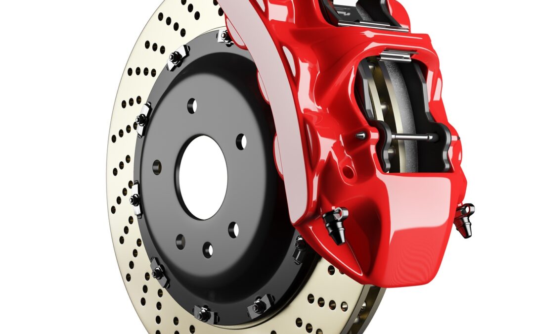
During the operation of the system there are several variables that all impact on performance:
- The transfer of weight from the rear axles to the front axles, which requires a gradual modulation of pressure to the loaded wheels
- The “knee-point”1) at which the servo reduces the assistance as well as the ratio of assistance versus pedal effort
- Due to the pressure being applied, the pipes and hoses tend to expand and reduce line pressure for a given pedal travel (In extreme cases the driver may describe this as a “spongy pedal”)
1) The servo, or brake booster, provides a progressive assistance up to the knee point where the maximum vacuum assistance is received and any rise in output pressure beyond this point is only due to an increased pedal effort. If assistance was not reduced at this stage wheel-lockup would occur.
It should also be noted that with the introduction of multi-channel ABS many of the dynamic issues around wheel rotation and dynamic vs static friction have been taken care of, including pressure modulation due to the weight transfer under braking.
However the rapid cadence braking with the ABS engaged can create wildly fluctuating, and at times, extremely high line pressures which need to be determined, using high quality pressure transmitters strategically placed in critical lines, during development.
With operating line pressures in the region of 100 Bar it’s imperative that all components, including pipes and hoses, are designed to meet these pressures; and that the system does not exceed these specified values.
However this is also not that simple, when one considers that pipes and hoses of different cross sectional areas, with differing wall thicknesses could all produce similar braking performance, but some may be marginal on burst strength.
The only way this can be verified is through the accurate measurement of the line-pressure when the system is fully pressurized. Obviously these measured values must fall within the pipe and tube suppliers specifications.
Furthermore, it’s also important to measure line-pressure to confirm that the pedal leverage ratio can pressurize the system to about 80 Bar under severe braking conditions. If the desired pressure cannot be easily attained the pedal ratio must be increased until this pressure is achieved.
And when engineering the system engineers also need to select the correct master cylinder bore: One of the most common misconceptions is that a larger master cylinder will create more pressure. While a larger master cylinder creates a larger displacement, it takes more force to create the same pressure compared to a smaller bore.
While a larger master cylinder will take up system slack with less pedal stroke, it will take more force to create the same system pressure. The result after adding a larger master cylinder is a harder pedal which needs much more pedal pressure to create the same amount of braking force. For instance, moving from a 3/4″ master cylinder to a 1″ requires 77.7% more force on the push rod.
The objective in optimizing brake performance can only be achieved by balancing the entire system: Pedal force, system pressure and lever travel all need to be taken into account, and during the design and development phases manufacturers have come to rely on highly accurate pressure transmitters produced specifically for applications such as these.