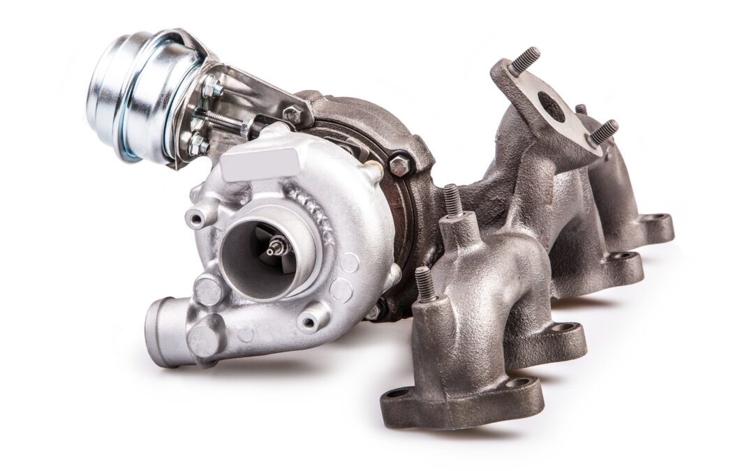
To meet ever tightening emissions legislation across the world OEMs are turning to downsized Spark Ignition engines. While these smaller engines consume less fuel and produce significantly lower emissions they require forced induction to deliver the performance drivers have come to expect from modern passenger vehicles.
The driveability of these downsized turbo engines must at least equal the performance of their naturally aspirated equivalents. This requires full boost pressure at low engine speeds without running out of steam at high speed, which can only be achieved with a sophisticated boost pressure control system.
The main problem with these forced induction spark ignition engines is the precise control of the air-fuel ratio near stoichiometric values at different boost pressures. At low speeds, these engines are prone to knock under medium to high loads.
Modern pressure control systems
Controlling the turbine-side bypass is the simplest form of boost pressure control.
Once a specific boost pressure is achieved, part of the exhaust gas flow is redirected around the turbine via a bypass. A spring-loaded diaphragm usually operates the wastegate which opens or closes the bypass in response to the boost pressure.
In recent times manufacturers have turned to variable turbine geometry to regulate boost pressure. This variable geometry allows the turbine flow cross-section to be varied to match the engine operating parameters.
At low engine speeds, the flow cross-section is reduced by closing the guide vanes. The boost pressure and hence the engine torque increases as a result of the higher pressure drop between turbine inlet and outlet. During acceleration from low speeds the vanes open and adapt to the corresponding engine requirements.
By regulating the turbine flow cross-section for each operating point the exhaust gas energy can be optimised, and as a result the efficiency of the turbocharger and therefore that of the engine is higher than that achieved with bypass control.
Today, electronic boost pressure regulation systems are increasingly used in modern Spark Ignition petrol engines. When compared with purely pneumatic control, which can only function as a full-load pressure limiter, a flexible boost pressure control allows an optimal part-load boost pressure setting.
The operation of the flap, or vanes, is subjected to a modulated control pressure instead of full boost pressure, using various parameters such as charge temperature, ignition timing advance and fuel quality.
Simulation reduces time to production and development costs
Faced with a plethora of complex variables, manufacturers have turned to simulation during the design and test phase.
A significant hurdle to overcome with downsized turbocharged engines is the narrow range within which the centrifugal compressor operates stably at high boost pressures.
The only way to build an effective simulation model is through extensive real world testing. This testing is mostly carried out on engine dynamometers in climatic chambers.
During wide open, and part throttle, runs the following pressure information is recorded:
- Intake manifold pressure
- Boost pressure
- Barometric pressure
Of course this is all integrated with engine temperatures (Coolant and oil) to gain a picture of engine performance over the full engine speed range.
During this testing it’s important that engineers note any abnormalities in performance, as events such as exhaust pulses at specific engine speed can set up standing waves which can excite the impeller at a critical frequency which will reduce the life of the turbo, or even lead to catastrophic failure.
Therefore the measurement of pressure performance maps of both compressor and turbine is vital for the creation of an accurate extrapolation model for implementation during simulation.
A well-developed simulation tool can save the OEM time and money in dynamometer and road tests, but can only be developed once the pressure maps have been completed.
