As a doctor measures blood pressure to determine the health of a patient, so too, the development engineer measures crankcase pressure to gain an insight into the condition of an engine on the test-bed. Not only does an increase in pressure provide an early indication of wear, but pressure measurement is crucial in the development of modern positive crankcase ventilation systems, that need to comply with emissions regulations.
It’s important to note that the measurement of crankcase pressure is not a direct measurement of “Blowby”, which is measured as a flowrate in standard cubic meters per second.
Measuring crankcase pressure to monitor cylinder liner, piston and ring wear.
Development engines are not cheap, taken that there’s usually an intensive engineering design program behind them: Therefore, the last thing any engineer wants to see is the test literally go up in smoke. To minimize the risk, testbeds nowadays are instrumented with a myriad of sensors to monitor everything from oil pressure and ambient temperature to EGTs and of particular interest, crankcase pressure.
Crankcase pressure sensors used on testbeds are particularly interesting as, not only are they capable of measuring relatively minor variances in pressure, but they are also stable across a wide temperature range whilst withstanding submersion in hot oil: This is particularly important as the sensor is often fitted to the sump or oil filler tube where it comes into direct contact with hot engine oil.
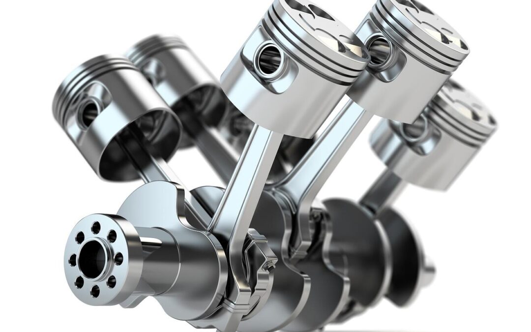
The piston-rings-cylinder (PRC) system is subjected to extreme stresses such as high frictional and accelerative forces, as well as extreme temperatures and pressures resulting from the combustion process.
Under these conditions there will always be some form of scavenging back into the crankcase, but as component wear increases, so will the pressure inside the engine. This is the basic principle behind measuring crankcase pressure as an early indication of wear on engines running on dynamometers or testbeds.
This increase of pressure in the crankcase in forced induction CI engines can be catastrophic, as the return of oil from the compressor will often be restricted resulting in the labyrinth seal failing causing a total loss of lubrication to the bearings.
Notwithstanding the importance of monitoring the PRC system’s condition, optimizing positive crankcase ventilation through accurate measurement of internal pressure is vital in meeting emissions legislation.
Designing the PCV for a cleaner environment.
In the early 1960s, General Motors identified crankcase gasses as a source of hydrocarbon emissions. They developed the PCV valve in an effort to help curb these emissions. This was the first real emissions control device fitted to a vehicle.
Ideally, the crankcase pressure should be controlled to just above atmospheric so that there’s enough pressure to exclude dust and moisture, but not enough to force oil past seals and gaskets; or on a forced induction engine, restrict the return of oil to the sump.
The first step in the design of an effective PCV valve is to determine the actual pressure in the crankcase by using a high quality pressure sensor specifically designed to accurately measure small differentials, whilst providing accurate repeatable readings across a wide temperature range.
Armed with the data accumulated during performance and durability runs, engineers are able to determine the appropriate parameters for the PCV valve:
- Suitable cross sectional area to facilitate sufficient vapour flow from the crankcase
- Correct operating pressure parameters to ensure unrestricted oil return on turbocharged engines, whilst retaining positive internal pressure.
Finally the prototype valve is evaluated on a testbed, again with crankcase pressure sensors fitted, to confirm performance and durability, as well as emissions compliance.
This development can span weeks and account for a sizeable chunk of the development bill, so the last thing a manufacturer would want is the failure of a vital sensor; which would require a partial, or even complete retest. That’s why OEMs only use high quality pressure transmitter, such as those produced by the pressure transmitter and transducer manufacturer STS.