Dependable fill-level control in coal mining

Dependable fill-level control in coal mining

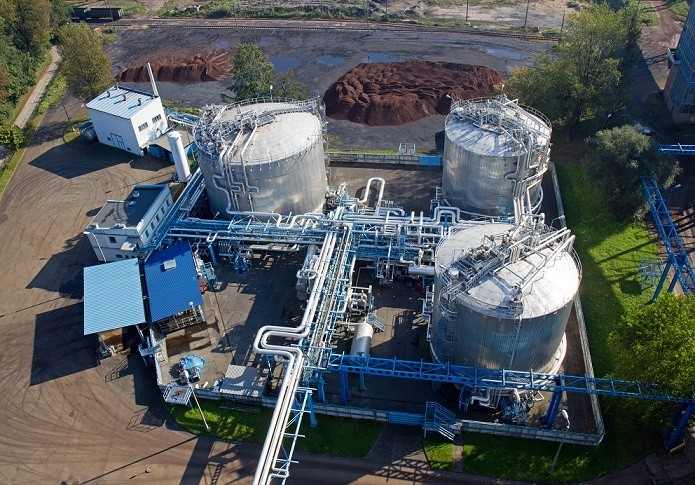
Mine workings and opencast pits are well known for their harsh working conditions. This applies equally to the technology deployed. For this reason, durable and reliable measuring instruments are required to monitor groundwater.

Ten percent of worldwide coal deposits are to be found in Australia. As the leading coal exporter, coal mining is one of the most important economic factors on that continent. Mining of the raw material, however, is not without its pitfalls. The operator of an Australian opencast approached STS as they were seeking a pressure transmitter for fill-level monitoring at depths of up to 400 meters.

Mining operations have a heavy influence upon groundwater. The aquifers surrounding the coal mine become drained, which leads to a sinking of the depression cone. This sinking alters the natural hydrological conditions underground by creating paths of lowered resistance. What this then leads to is water penetrating the open pit and underground workings. As a result, the constantly inflowing water needs to be continuously pumped out of the pit to ensure a smooth and safe extraction of the raw material.

To control the groundwater level and the pumps used for drainage, the operators of the opencast needed a pressure transmitter to monitor the fill-level according to their requirements. Stipulated was a pressure range from 0 to 40 bar (400 mH2O) ambient pressure, as well as a cable length of 400 meters. The solution offered by STS at that time, the ATM.ECO/N/EX, read only to 25 bar and had a cable length of 250 meters.

But since STS is specialized in customer-specific pressure measurement solutions, this challenge was to prove no major obstacle. In short time, the failsafe ATM.1ST/N/Ex pressure transmitter for fill-level was developed, which precisely meets the pressure requirements and is equipped with a 400-meter-long Teflon® cable. It is also convincing in its accuracy of just 0.1%. STS decided upon development of the new pressure transmitter for a Teflon® cable, a sealed cable gland and an open aeration tube (PUR is too soft for this). In addition, there is also a screw-on ballast weight to ensure a straight and stable measuring position. The stainless steel strain relief, which can also be screwed on, helps to relieve strain on the electrical cable. As the device designation indicates, it also carries the EX certification for use in explosive areas.

ATM.1ST/N/Ex with strain relief (left) and ballast weight (right), each screw-on.

Being an expert in customer-specific pressure transmitters, STS was able to supply the ATM.1ST/N/Ex in less than three weeks.

The features of the ATM.1ST/N/Ex in brief:

  • Pressure range: 1…250 mH2O
  • Accuracy: ≤ ± 0.1 / 0.05 % FS
  • Total error: ≤ ± 0.30 %FS (-5 … 50°C)
  • Operating temperature: -5…80 °C
  • Media temperature: -5…80 °C
  • Output signal: 4…20 mA
  • Materials: Stainless steel, titanium
  • Electronic compensation
  • Common process connections available
Hydrostatic level monitoring of tanks on piezoresistive basis

Hydrostatic level monitoring of tanks on piezoresistive basis

Hydrostatic pressure measurement is one of the most reliable and simplest methods for fill level monitoring in liquid-carrying tanks. In the following, we explain how hydrostatic level monitoring works and what users should consider here.

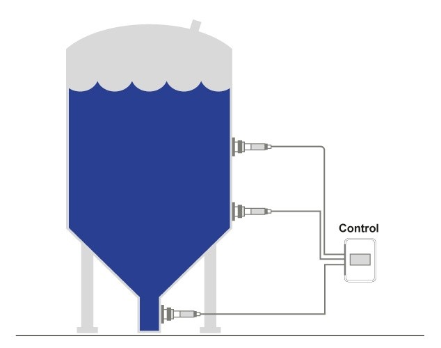
In hydrostatic level measurement, the filling level of a liquid in a container is to be measured. In this case, the force of weight acting on the pressure transducer installed at the bottom of the container is measured. The weight force in this context is termed the liquid column. It increases in proportion to the filling level and acts as a hydrostatic pressure on the measuring instrument. The specific gravity of the fluid must always be considered in hydrostatic level monitoring. The filling height is thus calculated with the following formula:

h = p/sg

In this formula, h stands for the filling height, p for the hydrostatic pressure at the base of the tank and sg is the specific gravity of the liquid.

The actual quantity of fluid plays no role in hydrostatic level monitoring, since only the filling height is decisive. This means that the hydrostatic pressure is identical in a 200 liter tank narrowing towards its base and in a straight sided tank containing 150 liters of liquid, as long as the liquid and the fill height are identical (3 meters, for example).

The simplest application of hydrostatic pressure measurement is when the liquid concerned is water, since the specific gravity can be disregarded altogether here. When a fluid other than water is involved, the pressure transmitter has to be correspondingly scaled to compensate for the specific gravity of that liquid. Once this has been done, the fill level can be determined, as with water, via the hydrostatic pressure on the bottom of the tank. It becomes more complicated when different liquids are used in a single tank. In this case, not only the hydrostatic pressure at the bottom of the tank must be measured, but at the same time the specific gravity of the respective fluid also. We will leave aside the latter case at this point and instead consider hydrostatic pressure measurement in both closed and open tanks.

Hydrostatic pressure measurement in open and closed tanks

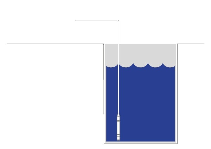
With open tanks, it does not matter whether they are above ground or set within it, as long as they have an opening that provides for a balanced air pressure inside and outside the tank. The measurement of the hydrostatic pressure can be carried out without further adjustments at the bottom of the tank. If measurement at the bottom of the tank is not possible, the filling level can also be found by means of a submersible probe, which is fed into the tank with a cable from above.

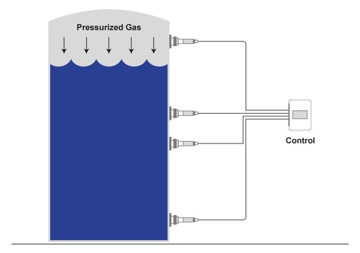
In closed tanks, higher gas pressures often prevail than in the atmosphere surrounding the tank. This gas layer above the liquid increases the pressure on the liquid itself. As a result, the liquid can flow off more quickly and there is also less loss due to evaporation. Tanks sealed from the ambient air are therefore frequently used in the oil and chemicals industries. The gas layer pushing down on the liquid also acts indirectly on the pressure transducer at the bottom of the tank and must therefore be taken into account in order to determine the correct filling level (a higher filling level than the actual would be indicated through this increased pressure). In closed containers, two pressures would therefore have to be measured: The gas pressure and the pressure at the bottom of the tank. The hydrostatic pressure of the fluid results from the difference between the measured gas pressure and the pressure measured at the base. This difference can then be converted into an indication of the fill level of the tank. For this type of application, a differential pressure sensor is generally used.

Concluding remarks

In hydrostatic level monitoring of tanks, two factors must always be considered: The type of fluid and the type of tank. The simplest application would be the monitoring of water levels in open tanks, since no adjustments have to be made for this constellation. If, however, a different liquid is involved, then the specific gravity of that liquid must also be taken into account. In addition, a measuring instrument is to be selected that can withstand the properties of the medium concerned. Whereas for most liquids stainless steel is sufficient as a housing material, highly corrosive media may also require different materials.

Hydrostatic pressure measurement with piezoresistive level sensors

Hydrostatic pressure measurement with piezoresistive level sensors

Whether as a life-giver, a danger to life or simply a refreshment in summertime, the element of water determines daily life on earth in many ways. Because of its sheer importance, a reliable monitoring of this element becomes essential.

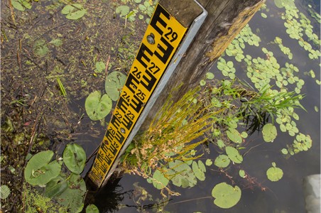
What cannot be measured can also not be managed efficiently. From fresh water supply, drinking water treatment, storage and consumption measurement, to waste water treatment and hydrometry, it will not be possible to work and plan efficiently without the correct input parameters. A range of devices and processes are now available to capture today’s complex hydrometric infrastructure. The classic in water level measurement is without doubt the level gauge, for which an accuracy of +/- 1 cm must be applied and which, of course, still functions completely “analog” – having to be inspected visually and doing without electronic data transmission. Today, far more advanced and precise instruments provide remote transmission of the measured data, including piezoresistive pressure sensors for water level measurement in both groundwater and surface waters.

Level measurement with pressure sensors

Pressure sensors for level measurement are installed at the bottom of the water body to be monitored. In contrast to level gauges, it is generally not possible to read them without getting wet. This is not necessary either, since piezoresistive level sensors were developed to meet today’s requirements for process automation and control. It goes without saying that water levels can thus be measured without human intervention, which makes continuous monitoring at difficult-to-access locations possible in the first place.

Hydrostatic level sensors measure the hydrostatic pressure at the bottom of the water body, where the hydrostatic pressure remains proportional to the height of the liquid column. Additionally, it is dependent upon the density of the liquid and gravitational force. According to Pascal’s law, this results in the following calculation formula:

p(h) = ρ * g * h + p0

p(h) = hydrostatic pressure
ρ = density of the liquid
g = gravitational force
h = height of the liquid column

Important considerations for trouble-free level monitoring

Because piezoresistive level sensors are placed at the bottom of the water body, they are then protected from surface influences. Neither foam nor flotsam can now influence the measurements. But, of course, they do have to be adapted to the expected underwater conditions. For salt water, for example, a level sensor with a titanium housing is to be preferred. Should galvanic effects be expected, however, then a measuring device of PVDF would be the best choice. In most freshwaters, high-quality stainless steel will be sufficient. And lastly, a sufficient grounding of the level sensors is essential to prevent damage from lightning strikes, for example (read more on this topic here).

Modern level sensors: All data from just one device

Piezoresistive level sensors can be used for level monitoring in open waters such as lakes, in groundwater occurrences and also in closed tanks. In open waters, relative pressure sensors will be used. With these devices, air pressure compensation is provided by a capillary inside the pressure sensor cable. A differential pressure sensor is normally used in tanks, since the gas overlay pressing down on the liquid must also be taken into account (read more on this topic here).

Because piezoresistive level sensors are largely self-sufficient and can also be optimized for very high pressures, measurements at great depths now become a possibility. Theoretically, there are hardly any limits to this depth, only that the pressure sensor cable has to be long enough.

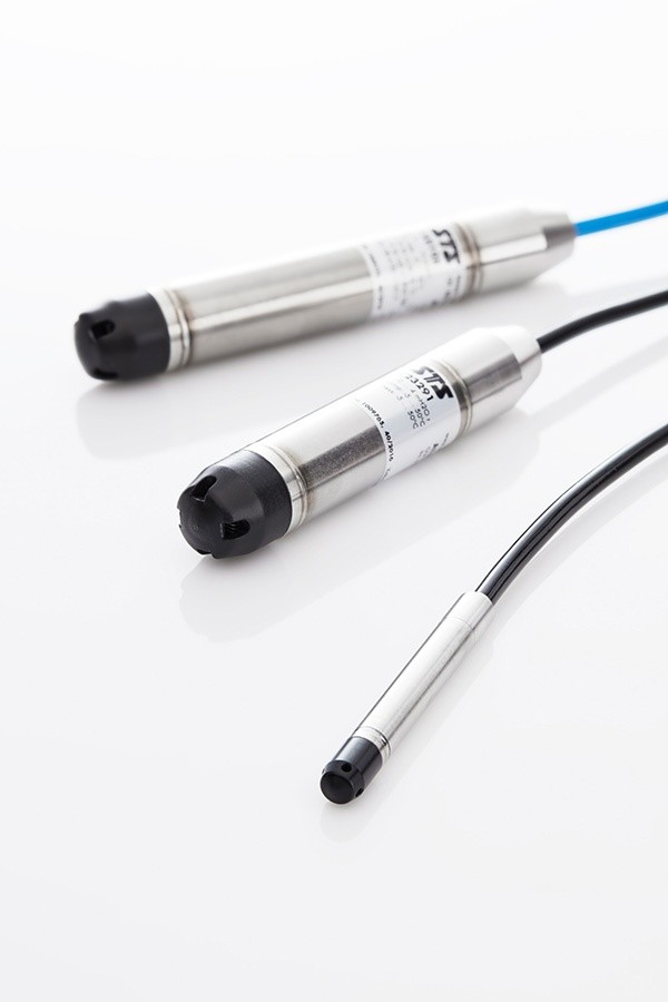
Figure 1: Examples of level sensors for hydrostatic pressure measurement

Apart from the fact that there are hardly any depth limits, these modern measuring instruments are also extremely versatile. After all, it is not only the level of a water body that is of interest to us. Water quality is also of great importance for groundwater monitoring. The purity of a groundwater reservoir, for example, can also be determined by its conductivity, where the lower the conductivity, the purer the water will be (read more about conductivity here). In addition to conductivity sensors, level probes today are now also available with integrated temperature measurement. Piezoresistive level sensors provide a wide range of monitoring tasks and are without question preferable to the level gauge in most cases.

Level monitoring for pump control in rainwater and wastewater tanks

Level monitoring for pump control in rainwater and wastewater tanks

Water supply and wastewater disposal vary according to local conditions. In Belgian buildings, many cellars are situated deeper than the sewage system. Wastewater disposal here must therefore be regulated by pumps.

The Belgian company Pumptech provides home owners and caretakers with powerful industrial pumps, through which water circulation within the buildings is partly regulated. This is essential in various regions of Belgium, because the cellars in the buildings there are often located beneath the sewage system.

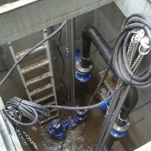
Since this wastewater cannot flow directly into the sewage system, however, it is temporarily stored inside tanks. Rainwater is also often collected in these buildings and then used for sanitary facilities. The rainwater hitting the roof is fed into underground tanks where it remains available for further use. As wastewater, it finally flows into the separate wastewater tanks, from where it is then pumped into the sewage system.

Whether in these wastewater or rainwater tanks, monitoring of the levels is essential for a regulated operation of the pumps. For this purpose, Pumptech has been using ATM.ECO/N submersible probes for 15 years now. Originally, level monitoring was performed here by float switches. As it turned out over time, this was an unsatisfactory solution – especially in regards the wastewater tanks. The big disadvantage of float switches in comparison to immersion probes is that they quickly become dirty due to impurities floating on the water surface and will then no longer work properly. This can have far-reaching consequences, since the pumps themselves are controlled by measurement of the filling level. Usually there are two to three pumps inside the tanks. When a predetermined level is exceeded, the first pump starts operation, with the second pump cutting in at the next fixed level. Alarms can also be triggered should certain limits be reached

Submersible probes, which are usually installed at the bottom of the tank, are not particularly susceptible to waterborne contamination. Once Pumptech had tested various suppliers, their choice eventually fell on the analogue level probe ATM.ECO/N from STS, since these best met their requirements when compared to competitors in regards their required long-term stability. Since then, these pump controls have been working away without incident.

The ATM.ECO/N immersion probes boast a fully sealed membrane made of high-quality stainless steel. A moisture filter on the pressure connection cable also prevents water or other contaminants from entering its measuring cell. A further advantage is the far better reaction time when compared to the previous float switch solution, which now allows users to see immediately what is happening inside the tanks.

You can find the data sheet for the ATM.ECO/N level probe here.

Grounding level sensors for protection from surges

Grounding level sensors for protection from surges

When monitoring filling levels, make sure that the level sensors are sufficiently grounded in order to prevent serious damage. Should this be inadequate or absent altogether can lead to three serious effects.

  1. Because of insufficient potential equalization in conductive media such as water, corrosion can occur. This is a gradual process, which can be observed in long-term applications. The voltage differences between the sensor and its surrounding fluid lead to electrolytic corrosion. The metal housing becomes gradually perforated and liquid then penetrates into the housing itself. Damage to the electronics will then be the consequence here. This process can be observed both in open waters and in fill level monitoring within vessels, where the potential difference between the level sensor, medium and vessel wall can cause electrochemical corrosion.
  2. Filling level sensors are connected to the control system by cables or plugged into telemetric systems. Through these connections, atmospheric voltages can be passed on to the sensor. Overstrain to the electronics will be the end result in this case.
  3. If lightning strikes near the level probe, a very high voltage difference will exist over the shorter term. The increased voltage in the water will then seek the shortest path to earth here via the level sensor.

Grounding and lightning protection of level sensors

To protect level sensors from these effects, they can be equipped with lightning protection. For this purpose, a transient overvoltage protection is integrated into the level probe, which will react to rapidly rising voltage differences. Should a sudden voltage surge occur, the lightning arrester will trigger a short circuit within the electrical circuitry to channel that overvoltage to ground. This surge protector normally operates in a non-conductive state, but does conduct voltage transients so that they can flow to ground without causing any damage. It should be noted, however, that with a direct lightning strike to the immersion probe, even overvoltage protection cannot prevent damage.

Additionally, an earth connection that should have a resistance of less than 100 ohms is used for grounding. For fill level monitoring in liquid-carrying tanks made of metal or even plastic, care must be taken that all of the isolated metallic components are connected together to ground. In open waters, a greater effort is generally required to create a low resistance to ground. For this reason, an earthing grid is often set into the ground for these applications.

Users are generally advised to discuss a grounding concept with the manufacturers in regard to their respective application.

Subscribe To Our Newsletter

Join our mailing list to receive the latest news and updates from our team.

You have Successfully Subscribed!