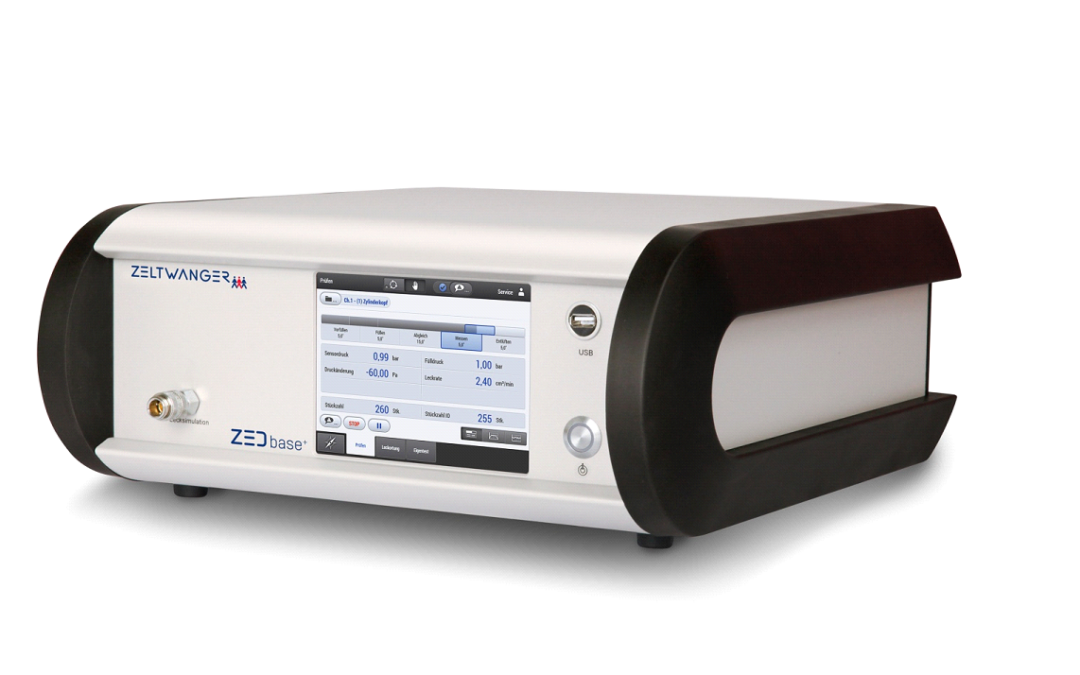
Accurate pressure measurement is crucial to developing an electric oil pump
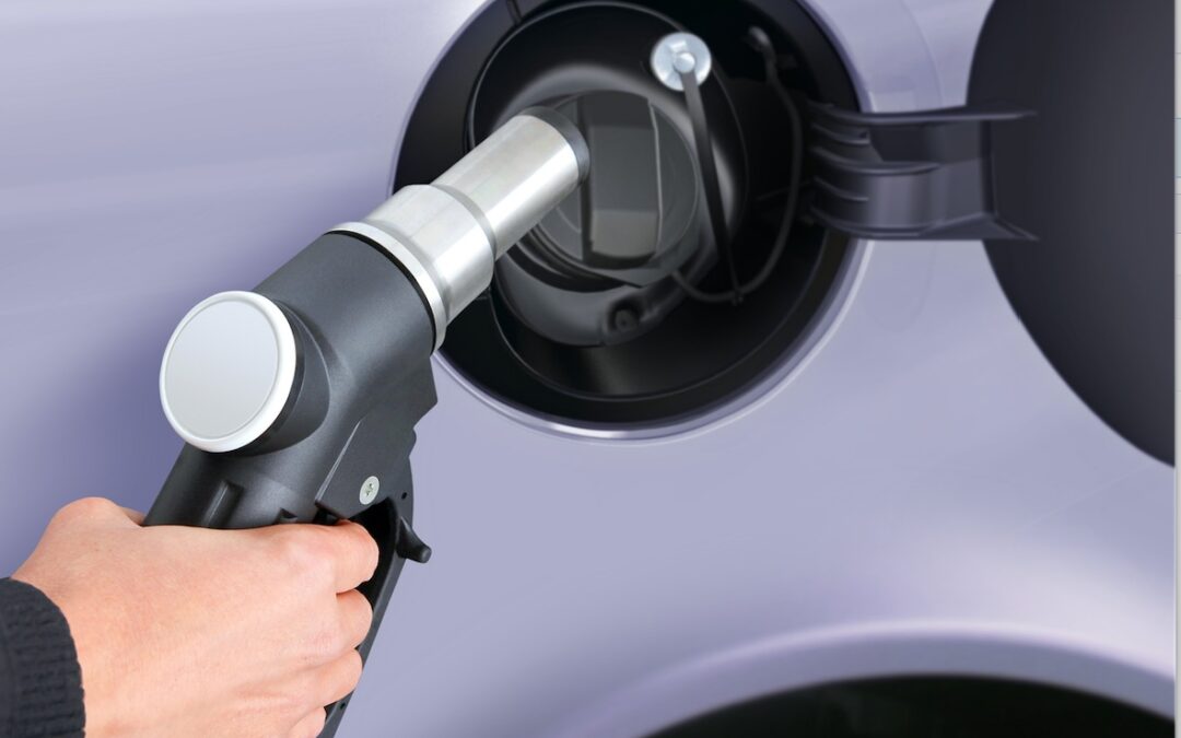
Driven by escalating global emissions targets, OEMs are increasingly turning to electrification to reduce fuel consumption and Greenhouse Gas emissions. A popular choice in this regard is the hybrid electric vehicle, often powered by a severely downsized engine.
The problem with these downsized engines is that power-sapping auxiliary systems severely impair drivability and performance. Fortunately these parasitic losses can be significantly reduced by replacing traditionally mechanical components with electrically driven units. Because of this, electrically powered pumps are rapidly finding their way into series production; particularly driving oil and water pumps.

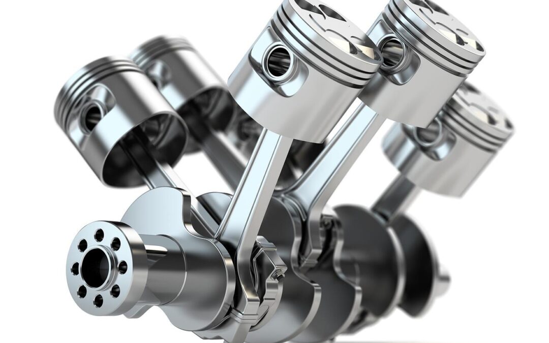
Image 1: Example of an electric oil pump
Image Source: Rheinmetall Automotive
But while the benefits are obvious, electrifying, in particular the oil pump, is technically complex: Engineers, not only wish to circulate the oil at a particular flow rate and pressure, but would like to intelligently match these to the engine requirements.
In order to optimize the performance it’s important that friction and pumping losses are minimized through careful control of the oil flow into different branches of the oil circuit while ensuring the correct pressure is available at all times.
Simulation relies on accurate testbed oil pressure and flow rate information
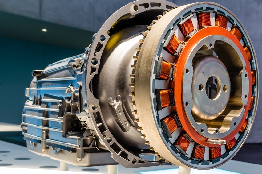
An electrically powered oil pump is made up of three subsystems – the pump, motor and electronic controller. Therefore the primary challenge of any new application development is the efficient integration of these modules so as to reduce the overall size and weight as well as the number of components, whilst optimizing performance.
The main function of the oil pump is to deliver a specified oil flow at an optimal pressure. For this reason, its design, which is an iterative process, starts with the ‘pumping gears’. For most applications the pump is required to deliver pressures in excess of 1 to 2 bar, often going as high as 10 bar.
As in most engine developments, a combination of simulation and real world testing is used to speed up the design.
The design loop begins with the preliminary assessment of the volumetric efficiency based on experimental results collected on similar pumps and applications. These include pump speed, oil temperature, pressure and flow rate.
It’s important that the information used for the estimation is accurate, therefore the data collection must be carried out using highly dependable, precise measuring equipment that can deliver accurate readings under the extreme conditions encountered in and around the engine.
To ensure accuracy and repeatability it’s important that only the best quality sensors are used when measuring the pressure. Not only must these pressure sensors provide reliable readings across a wide range of pressures and temperatures, but they must also withstand vibration.
Over many years STS have developed pressure sensors that meet OEM, first tier and specialist engine designers’ requirements in engine development.
Developing an electric oil pump that outperforms the mechanical unit
Armed with the information gathered on the hydraulic requirements at various flow rates, delivery pressures and oil temperatures, a preliminary design of the gears is finalized. Using Matlab’s Simulink software, the information regarding the behavior of the physical system can be rationalized into an one-dimensional code.
At this stage it’s important to note that to generate the required flow at a specified pressure, a rotational speed should be selected that facilitates the best packaging of motor and pump without creating cavitation or noise issues: Thus a typical speed range for continuous operation is usually between 1500 and 3500 rpm.
In the next step, several designs can be generated using LMS Imagine. Lab’s Amesim software that optimizes the design parameters – for example the number of teeth and eccentricity, while satisfying all pressure, flow and temperature boundary conditions.
After implementing the geometrical features of the calculated hydraulics and the interim design has been finalized the total torque required to drive the pump at critical working points can be calculated as follows:
Mtot = MH + MCL + Mμ
Where:
- MH is the hydraulic torque due to the generation of required pressure and flow
- MCL is the coulombian contribution generated where there are dry or lubricated contacts between sliding parts
- Mμ is the viscous contribution due to the fluid movement inside clearances.
Once the design is completed, engineering prototypes are constructed for real world evaluation on an engine testbed.
Once again oil pressure, flow rate and temperature are measured at various engine and pump speeds to validate the results obtained through simulation. If the results meet the specifications the development program is finalized and the project enters the industrialization phase.
For optimal performance and durability it’s obvious that all measurements be accurately recorded, but the weight given to information generated by the pressure sensor possibly outweighs all others – insufficient pressure at any point can lead to a catastrophic failure; while excessive pressure wastes energy and could lead to problems with the oil seals.