As the “Cool War” hots up, so the pressure increases

As the “Cool War” hots up, so the pressure increases

Sustainable automotive air conditioning has been the subject of a heated debate over the past few years: The debate, nicknamed the “Cool War” has focused on the next-generation refrigerant to be used in car air conditioning.

The Alliance for CO2 Solutions and its supporters, scientists, NGOs and business leaders, have advocated that the motor industry replaces global warming chemical compounds such as R134a, with the natural refrigerant, carbon dioxide (CO2, R744/ R-744).

The change, they argue, will reduce vehicle pollutants by 10%, and cut total greenhouse gas emissions by 1% worldwide. If CO2 Technology is applied in other sectors, such as commercial and industrial refrigeration, heat pumps for water heating, etc. it may even eradicate up to 3% of the world’s greenhouse gasses.

However, the opposition’s juxtaposition also has merit: Refrigerants such as the Greenpeace-developed ‘Greenfreeze’, based on purified butane/propane mixtures, are entirely ‘natural,’ and due to increased efficiency over refrigerants such as R134a, allow for tiny amounts of refrigerant to be used.

And, the use of pure hydrocarbon refrigerants, which are ‘backward compatible’ with earlier Freon (R-12) car air conditioning systems, would allow these systems to be easily converted, increasing their efficiency, and preventing further release of harmful R-134a and R-12 into the atmosphere.

Unlike the Greenfreeze and hydrocarbon based air conditioners, motor vehicle air conditioner systems that run on R744 require a complete redesign to cope with pressures in excess of 100 Bar. Existing system components such as seals, hoses, valves and even compressors were never designed to operate under these conditions. And to make matters worse, the EU decreed that R134a be discontinued by January 2017.

Fortunately, there is another alternative: DuPont and Honeywell have already developed Hydrofluoroolefin (HFO)-1234yf in response to the 2006 EU directive requiring all new vehicles sold in the EU be equipped with low global warming potential (GWP) refrigerants. The limit was set at a GWP value of 150, which R1234yf meets easily. Further, it decomposes in the atmosphere in about eleven days, and the Life Cycle Climate Performance calculation, a model, certified by the US Environmental Protection Agency, confirms it’s one of “the most sustainable refrigerants for worldwide use.”

However, there is growing concern over the flammability of R1234yf; even prompting Mercedes-Benz to install a dedicated “cooling system” to dowse engine hotspots in the case of an accident that may lead to the evacuation of the A/C system.

With the notable exception of the E and S class, all new Mercedes-Benz vehicles will convert to R1234yz refrigerant from January 2017: The E and S classes will be the first series production vehicles fitted with the COair conditioning systems.

The reason that these top end models are equipped with CO2 charged air conditioners first, is because of the development time and cost to re-engineer the complete systems and effectively test them.

The extremely high system pressure and optimized component packaging required extensive qualification of the system. Of particular concern was the performance of the condenser, evaporator, pipes and hoses, and seals under the significantly higher operating pressures.

During development, accurately measuring the line pressure with pressure transmitters at critical points in the air conditioner was crucial in ensuring the integrity of the system; a drop in pressure would be an early indication of a component such as a seal failing, thus requiring a redesign. Accurately measuring pressure drop over the evaporator was also important to verify the design parameters and efficiency of the component.

However with most of the elements in the system having “shrunk” in size, placing a pressure sensor exactly where it was required was never going to be easy. Nevertheless, by using quality piezoresistive pressure sensors during development the problem was quickly overcome and the project was able to be completed in time to meet the January 2017 rollout.
Braking systems work best under pressure

Braking systems work best under pressure

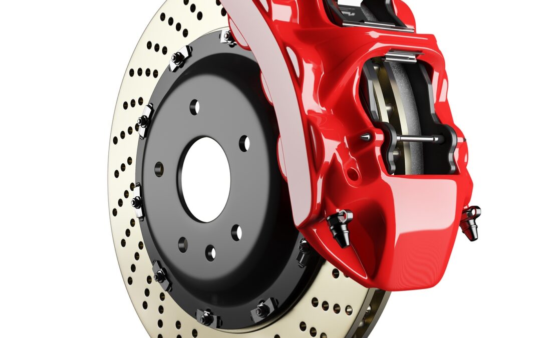
Although some high-end vehicles are moving away from hydraulically activated braking systems to hybrid brake-by-wire versions, most drivers still rely on hydraulic pressure to bring them to a stop.

Even though vehicles have been equipped with hydraulic braking systems for decades, developing a system that delivers feedback to the driver whilst retaining effective retardation at all times and under all conditions is extremely challenging.

During the operation of the system there are several variables that all impact on performance:

  • The transfer of weight from the rear axles to the front axles, which requires a gradual modulation of pressure to the loaded wheels
  • The “knee-point”1) at which the servo reduces the assistance as well as the ratio of assistance versus pedal effort
  • Due to the pressure being applied, the pipes and hoses tend to expand and reduce line pressure for a given pedal travel (In extreme cases the driver may describe this as a “spongy pedal”)

1) The servo, or brake booster, provides a progressive assistance up to the knee point where the maximum vacuum assistance is received and any rise in output pressure beyond this point is only due to an increased pedal effort. If assistance was not reduced at this stage wheel-lockup would occur.

It should also be noted that with the introduction of multi-channel ABS many of the dynamic issues around wheel rotation and dynamic vs static friction have been taken care of, including pressure modulation due to the weight transfer under braking.

However the rapid cadence braking with the ABS engaged can create wildly fluctuating, and at times, extremely high line pressures which need to be determined, using high quality pressure transmitters strategically placed in critical lines, during development.

With operating line pressures in the region of 100 Bar it’s imperative that all components, including pipes and hoses, are designed to meet these pressures; and that the system does not exceed these specified values.

However this is also not that simple, when one considers that pipes and hoses of different cross sectional areas, with differing wall thicknesses could all produce similar braking performance, but some may be marginal on burst strength.

The only way this can be verified is through the accurate measurement of the line-pressure when the system is fully pressurized. Obviously these measured values must fall within the pipe and tube suppliers specifications.

Furthermore, it’s also important to measure line-pressure to confirm that the pedal leverage ratio can pressurize the system to about 80 Bar under severe braking conditions. If the desired pressure cannot be easily attained the pedal ratio must be increased until this pressure is achieved.

And when engineering the system engineers also need to select the correct master cylinder bore: One of the most common misconceptions is that a larger master cylinder will create more pressure. While a larger master cylinder creates a larger displacement, it takes more force to create the same pressure compared to a smaller bore.

While a larger master cylinder will take up system slack with less pedal stroke, it will take more force to create the same system pressure. The result after adding a larger master cylinder is a harder pedal which needs much more pedal pressure to create the same amount of braking force. For instance, moving from a 3/4″ master cylinder to a 1″ requires 77.7% more force on the push rod.

The objective in optimizing brake performance can only be achieved by balancing the entire system: Pedal force, system pressure and lever travel all need to be taken into account, and during the design and development phases manufacturers have come to rely on highly accurate pressure transmitters produced specifically for applications such as these.

Automatic transmissions thrive under pressure

Automatic transmissions thrive under pressure

Although several attempts were made to design a transmission that selected gears automatically, it wasn’t until 1939 that the engineers at General Motors came up with a satisfactory solution; the device was called HydraMatic, and it was the first fully automatic passenger car transmission to reach production, with about 25,000 Oldsmobiles equipped with them being sold.

Nearly twenty-five years later, in 1963, Earl A. Thompson who had been in charge of the group of GM engineers which developed the HydraMatic, received the Sperry Award, in recognition of “a distinguished engineering contribution which, through application, proved in actual service, has advanced the art of transportation whether by land, sea, or air.”

Over the next 75 years, the Automatic Transmission (A/T) gained another five (Or even six) speeds, become electronically controlled and shrunk in size. But after all these years the A/T still relies on hydraulic line pressure to function.

Hydraulic line pressure controls the behavior of the automatic transmission 

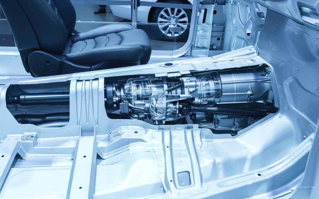
The valve body is the control center of the automatic transmission.  It contains a maze of channels and passages that direct hydraulic fluid to the numerous valves which then activate the appropriate clutch pack or band servo to shift to the right gear for each driving condition smoothly.

Each of the many valves in the valve body has a particular purpose and is named for that function. For example, the 2-3 shift valve activates the 2nd gear to 3rd gear up-shift, or the 3-2 shift timing valve which determines when a downshift should occur.

The most important valve is the manual valve which is directly connected to the gear shift lever and covers and opens various passages depending on what position the gear shift is placed in.  When in Drive, for instance, the manual valve directs fluid to the clutch pack(s) that activates 1st gear. It’s also setup to monitor vehicle speed and throttle position so that it can determine the optimal time and force (Dependent on engine load and speed) for the 1 – 2 shift.

On computer controlled transmissions electrical solenoids are fitted to the valve body which direct fluid to the appropriate clutch packs or bands under computer control to more precisely control shift points.

The pressure generated by the oil pump is channeled to mainline, governor, and throttle pressure valves to control and lubricate the transmission. Some of these have been replaced or work together with electronic controls.

  • Governor pressure increases with vehicle speed. Older transmissions had mechanical governors that consisted of springs, centrifugal weights, and a spool valve to control this pressure. Governor pressure determines the transmission upshift whilst throttle pressure decides the downshift. Today’s transmissions use solenoids for shift timing.
  • Throttle pressure indicates engine load. Some transmissions use a vacuum modulator or throttle linkage to control the throttle valve. Late model vehicles use electric solenoids to achieve the same results.

Transmissions change gears by moving shift valves. Governor pressure works on one end of the valve and throttle pressure aided by a spring operates on the other. When a vehicle first accelerates from a stop, throttle pressure is higher than governor pressure, so the car stays in first gear. As vehicle speed increases, the governor pressure (affected by vehicle speed) increases until it overcomes throttle pressure and causes an upshift.

A downshift occurs when throttle pressure overcomes governor pressure. This is because of the increased engine load. These two pressures control shift valve movement. Shift valves control the reactionary devices (clutches and bands) that drive and clamp members of the planetary gear set.

To achieve a smooth gear-change without excessive “slip” is no mean feat: The pressure, locking one set of bands and releasing another, has to, not only be correctly timed but has to be applied in a manner that gives a firm shift without shock. This is all controlled through the hydraulic line pressure.

During development of the A/T port line pressures are measured in real time and compared to design norms to confirm that design parameters are being met. At the same time, shift times and quality are measured and subjectively evaluated to ensure driveability and performance goals are achieved. This can only be done through highly accurate, quality pressure transmitters such as those produced by STS.

These measurements recorded during development are critical, not only for establishing quality shifts but also for developing unique specifications pertaining to the particular transmission. These are used for fault diagnosis at repair shops.

Keeping pace with the times

With emissions regulations playing a significant role in the development of modern vehicles, manufacturers continue to rethink the design, with an eye on improving efficiencies without detracting from performance.

In one such development undertaken by Korean manufacturer KIA, 143 new technologies were patented during the design of the compact 8AT. This new transmission enables smooth acceleration from a standstill, as well as greater fuel efficiency, improved NVH characteristics, and more decisive acceleration at high speeds than an automatic transmission with fewer gears.

To improve the eight-speed automatic transmission’s fuel economy, KIA engineers significantly reduced the size of the oil pump (the primary source of power loss in an automatic transmission) and simplified the structure of the valve body. Boasting the smallest oil pump of any production transmission in its class, the 8AT is able to use hydraulic oil more efficiently, distributing it evenly throughout the unit at all times.

KIA’s development teams also incorporated a direct control valve body to allow solenoid control of the clutch directly, rather than via several control valves. This enabled KIA to reduce the number of control valves from 20 to 12, resulting in quicker gear shifts, a more direct mechanical link to the engine and improved packaging.

The challenge in this revolutionary approach was to ensure that the smaller pump was capable of supplying sufficient volumes of hydraulic fluid at pressures up to about 20 bar to the various components required for the operation of the A/T.

During developmental tests the mainline pressures were measured under idle and wide open throttle conditions, with the unit at operating temperature, to ensure that the smaller pump was up to the task. Once again, because of the critical nature of the results obtained from these tests only high-quality laboratory certified pressure transmitters were used.

Smoother than a Roller, better than a race car: Active suspension comes of age

Smoother than a Roller, better than a race car: Active suspension comes of age

Colin Chapman is regarded as an automotive visionary in racing circles: His two noteworthy achievements in the technological stratosphere known as Formula One racing, were the development of “Ground effects” and “Active suspension.” Both of which were subsequently banned from F1, but adopted and developed for road cars.

Even the early road going iterations of the Chapman penned active suspension showed significant gains over their semi-active counterparts.

However the early Lotus system, which used hydraulic rams to move the wheels, cost thousands of dollars, added 150 Kilograms, and required about four Kilowatt to drive the system’s 140 Bar hydraulic pump. Furthermore, the system couldn’t respond quickly enough to smooth out the small sharp bumps that plague most roads.

Active suspension relies on accurate pressure measurement during development

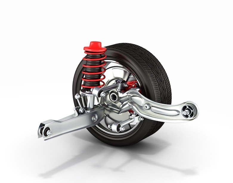
In trying to smooth out the bumps in developing hydraulically interconnected suspension (HIS) it was obvious that the optimization of the system lay with control and response of the actuators that regulated the wheel movement. Not only did these need to generate the forces involved in supporting the car, traversing rough terrain and negotiating turns in the road, but they also had to react in a fraction of a second: And key to this was the operating pressure of the system and how this was controlled.

To achieve the performance and response targets engineers had to overcome several challenges, including:

  • Hydraulic fluid used to drive the system never operates at a constant temperature and viscosity, thereby impacting on the delivery pressures.
  • Precise control of the appropriate pressure relied on extremely accurate real time line-pressure measurement, with temperature compensation.

The pressure sensors used during development had to be of laboratory quality and have a very quick response to changes in pressure. Even today there are only a handful of manufacturers that are capable of manufacturing these high quality components to the standards required by the industry.

Although the hydro-mechanical HIS active suspension improved exponentially, the costs involved in achieving the response time were staggering, limiting the systems to a few top-end sports and luxury cars.

Finally smart control ushers in intelligent suspension

It wasn’t long before manufacturers began turning to electronic processors and control units to exercise precise control over the hydraulics controlling the actuators. This has finally empowered the engineers to precisely control the pressure routed to individual actuators thereby improving response time and performance over a wide range of operating conditions.

That’s exactly what Mercedes Benz’s Magic Body Control (MBC) does. A camera situated at the top of the windshield scans the road ahead, analyzing its flaws and blemishes, and feeds that data directly to the Active Body Control (ABC) system’s control unit. The camera scans the area 4.5 to 13.5 Meters in front of the car, and can detect and measure imperfections as small as 10mm. In doing so, the system knows exactly what the tires will encounter, fractions of a second before the event. This allows the active suspension time to prepare the suspension for the appropriate ride-control.

Using the input from the cameras the MBC can even “retract” a wheel prior to impact with a pothole, thereby preventing the wheel from dropping all the way into the hole. This obviously does a great deal to lessen the impact and improve the ride quality.

Even though active suspension has been integrated into the larger ADAS (Advanced Driver Assist Systems) architecture, many systems still rely on the precise control of the hydraulic line pressure to achieve the desired ride and handling. And at the root of this is a high quality pressure sensor that provided the development engineers with accurate data, upon which they could base the algorithms that control the modern active suspension system.

It’s time to rethink engine cooling

It’s time to rethink engine cooling

All internal combustion engines experience significant energy “loss” due to the inefficient conversion of chemical energy into heat and subsequently, kinetic energy. Even a modern F1 engine is relatively wasteful when it comes to converting the power available from the fuel/air mixture into power at the rear wheels. This is measured in terms of ‘thermal efficiency,’ and is typically in the region of 30%: that’s to say, if a typical F1 engine produces slightly under 650 KW on the dyno, something like another 1500 KW does no work in propelling the car.

So where does it go? A small percentage is turned into the distinctive sound of an F1 car. The vast majority, though, must be dissipated as heat from a number of areas: for example, the oil dispels around 120 KW and the water system 160 KW. The inefficiencies of the gearbox will mean it has to dissipate around 15 KW, while the hydraulics represent a further 3 KW.

In these high-performance engines, the coolant systems are commonly pressurized up to 3.75 bar and have a boiling point around 120°C.

In the modern passenger car, coolant system pressures are characteristically in the order of between 0.9 to 1.1 bar, raising the boiling point by about 22°C  resulting in an engine coolant operating temperature of about 100°C.

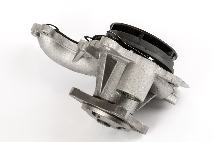
At the same time, a typical water pump can move a maximum of about 28,000 liters of coolant per hour, or recirculate the coolant in the engine over 20 times per minute, whilst drawing off up to 2 KW in parasitic losses.

These figures are well known and have been used as a rule of thumb by automotive engineers for over 100 years: But downsizing to meet ever tightening emissions requirements, and the proliferation of hybrid electric vehicles are changing the rules.

Going electric saves power, but beware the pressure

Manufacturers are studying, in depth, all parasitic losses in an endeavor to increase the efficiency of current and future powertrains. This includes a relook at the coolant system, and in particular the mechanical water pump.

Whilst the decoupling of the water pump from the engine achieves significant savings, it basically requires a requalification of the entire cooling system’s performance; including the operating pressures under varying temperatures, and engine speeds.

With the delivery of the electric motor no longer directly proportional to the engine speed, but rather dependent on the engine’s requirement it’s important that, during development, the cooling system pressure be monitored at all times. This ensures that components such as the radiator and water hoses remain in the safe operating zones.

During the development of what is principally a new technology, mapping the system’s pressure requires highly responsive pressure sensors of unquestionable quality and accuracy. There are a handful of specialist pressure transmitter manufacturers that meet all these requirements.

While these sensors have to accurately record data, they also need to be robust: The operating environment demands that they function faultlessly over a wide temperature range, and withstand vibration and exposure to chemicals.

Although currently mostly fitted to high-end models such as BMW and Mercedes Benz, this technology will rollout to other segments as new models come to market. And all of these will have undergone the same stringent cooling system qualification to ensure durability and safeguard the very costly engine.

Subscribe To Our Newsletter

Join our mailing list to receive the latest news and updates from our team.

You have Successfully Subscribed!