Accurate pressure measurement plays a vital role in the early days of automotive fuel cells

Accurate pressure measurement plays a vital role in the early days of automotive fuel cells

While Electric and hybrid EVs are firmly entrenched as maturing technologies much development is still needed in storing the electrical energy in a safe, convenient and cost effective manner. As a potential solution to expensive storage batteries most manufacturers around the world are studying ways of harnessing hydrogen to generate electricity to drive the electric traction motors.

Hydrogen fuel cells employing proton exchange membranes, also known as polymer electrolyte membrane (PEM) fuel cells (PEMFC), have already seen limited series production in vehicles such as Toyota’s Mirai. 

Fuel cells consist of MEAs (membrane electrode assemblies) sandwiched between separators. An MEA is a solid polymer electrolyte membrane with catalyst layers applied to it.

These cells generate electricity through a chemical reaction between hydrogen and oxygen: Hydrogen and ambient air are respectively supplied to the anode (negative electrode) and the cathode (positive electrode) of fuel cells to generate electricity.

Since one cell yields less than one volt, several hundred cells are connected in a series to increase the voltage. This combined body of cells is called a fuel cell stack. 

Furthermore, although small PEM fuel cells are operated at normal air pressure, larger fuel cells, of 10kW or more, are usually operated at higher pressures. The advantages and disadvantages of operating at higher pressure are complex, and the arguments are not at all clear-cut, with many convincing points of view on both sides. 

Supercharging the hydrogen fuel cell 

As with conventional Internal Combustion Engines, the purpose of increasing the pressure in a fuel stack is to increase the specific power, by extracting more power out of the same size cell. Ideally, the extra cost, size, and weight of the compressing equipment will be less than the cost, size, and weight of simply getting the extra power by increasing the size of the stack. 

In the case of ICEs the advantages clearly outweigh the disadvantages. However, with fuel cells the advantage/disadvantage balance is much narrower. Above all, this is because there is little energy in the exit gas of the PEMFC, and any compressor has to be driven largely or wholly using the precious electrical power produced by the fuel cell.
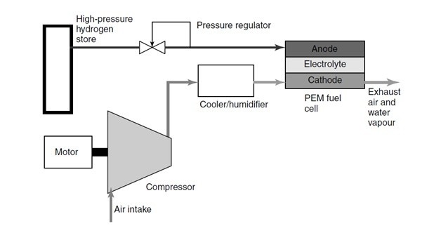
Image 1: Schematic of a fuel cell system
Image source: James Larminie, Andrew Dicks (Fuel Cell Systems Explained)

The simplest type of pressurized PEM fuel cell is that in which the hydrogen gas comes from a high-pressure cylinder. In this design only the air has to be compressed; the hydrogen gas is fed from a pressurized container, and thus it’s compression ‘comes free’. This method of feeding hydrogen to the anode is known as deadening; implying there is no venting or circulation of the gas – it is entirely consumed by the cell.

However, the compressor for the air must be driven by an electric motor, which of course uses up some of the valuable electricity generated by the fuel cell. Typically, for a 100kW system the power consumption will be about 20% of the fuel cell power. As in ICEs, for optimal efficiency the compressed air also needs to be cooled before entry into the PEM cell.

Balancing the pressure to optimize performance

As this is a young evolving technology the reliability and durability of these “supercharged” fuel cells need to be tested and developed if it is to be widely adopted. Hence there is considerable research and development taking place to improve the performance and lifespan.

Testing under controlled conditions is an important step towards the viability and uptake of fuel cells. Detailed measurement data is crucial as input information to create models of the fuel cell operation. Yet, in spite of widespread interest, suitable measurement techniques are still only in the process of being developed.

Typically the PEM fuel cell operates at pressures ranging from near ambient to about 3 bar and at temperatures between 50 and 90°C. High power density is achieved at higher operating pressures but the net system efficiency may be lower on account of the power needed to compress the air. Higher air temperatures also increase power density, but may pose a significant challenge for water and heat management, especially at lower operating pressures.

Therefore selection of operating temperature and pressure of the automotive PEM fuel cell system must be based on (a) high net system efficiency, (b) small component size, and (c) neutral or positive water balance so that the vehicle does not have to carry an on-board reservoir.

The increase in power resulting from operating a PEM fuel cell at higher pressure is mainly the result of the reduction in the cathode activation overvoltage, because the increased pressure raises the exchange current density, which has the apparent effect of lifting the open circuit voltage (OCV), as described by the Nernst equation.

However, as previously mentioned this supercharging comes at the expense of the power that the pressurized fuel cell produces, hence the importance of balancing the pressure to the requirements of the specific fuel cell. As with ICE boost pressures, this can only be done by taking accurate pressure measurements using high quality pressure sensors that are painstakingly calibrated to the environment.

These pressure measurements, recorded with laboratory grade sensors supplied by STS, are then compared to the fuel stack outputs to minimize the parasitic losses while optimizing the gains in electrical output.

As automotive hydrogen fuel cell technology matures and data collected from real-world trials is used to produce predictive models, engineers and researchers will no doubt gain a better understanding of the complex inter-relationship between, temperature, pressure and efficiency: But in the meantime this research will rely heavily on quality sensors recording accurate data.
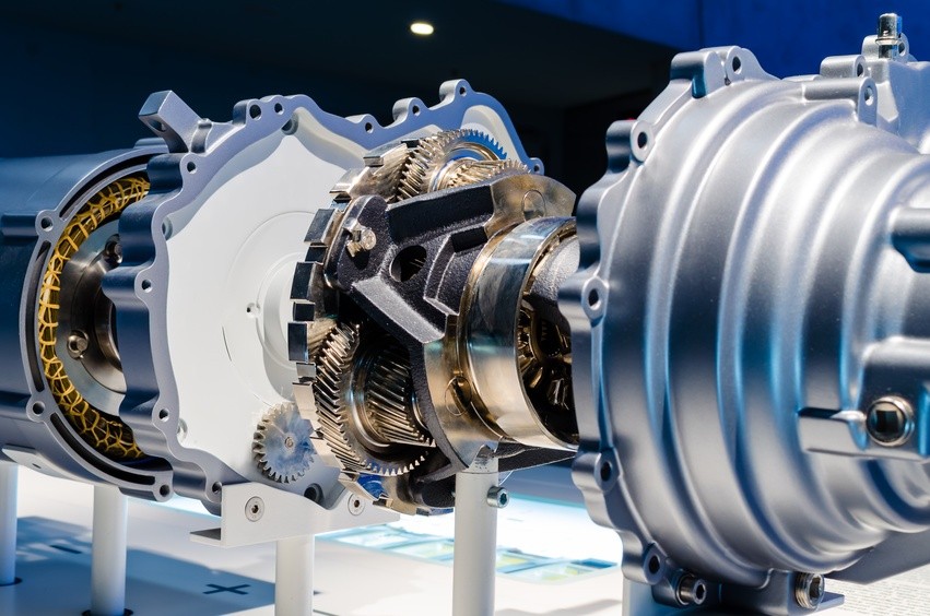
Accurate pressure measurement is critical to safe, cost-effective, motor vehicle development

Accurate pressure measurement is critical to safe, cost-effective, motor vehicle development

The principle of hydraulic power to carry out work has been around since ancient Egyptian times, but as systems have evolved, so too have the tools required to design and develop these sophisticated, often critical circuits.

From the earliest manometer invented by Evangelista Torricelli in the 1600’s to the mechanical Bourdon gauge and finally today, the piezoresistive pressure transducer, developers have always sought the best equipment to measure pressures and optimize the design. And in recent times automotive engineers, in particular, have come to rely on these high-quality, accurate pressure sensors when carrying out vehicle testing and development.

These current pressure transducers are typically capable of recording full-scale deflections from about 350 mbar to 700 bar under sustained temperatures ranging from -40OC to 150°C; and best of all, quality sensors such as those produced by STS, are capable of a hysteresis and repeatability of typically around 0.001%!

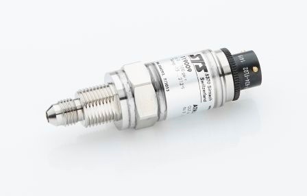
Image 1: High precision pressure transmitter ATM.1ST with accuracy of up to 0.05% FS

High-quality pressure sensors are used in the development of key automotive systems.

This level of repeatability is critical in the design and development of cooling and fuel delivery systems, amongst others. During development, designers rely on stable pressure measuring equipment to accurately record information so that the effect of even the smallest of design changes can be documented without concerns that the sensor is incapable of repeatable results.

In a recent redesign of an engine cooling system to take advantage of the reduced parasitic losses made possible through electrification, the engineering team at a luxury OEM was initially faced with a pressure drop across the pump of around 250kPa. Before a redesign of the new electric pump was possible, accurate pressure measurements had to be recorded allowing engineers the opportunity to identify the problem. After studying the results logged by the array of pressure sensors the design was modified, reducing the drop to less than 100kPa and cutting the parasitic losses by 500W.

And although electrification and electronic controls are playing increasingly significant roles in vehicle systems, hydraulic pressure is still relied upon to guarantee smooth operation of many critical circuits.

By way of example, during the development of an automatic transmission, port line pressures have to be measured in real time and then compared to design norms to confirm that design parameters are being met. At the same time, shift times and quality are measured and subjectively evaluated to ensure drivability and performance meet customer requirements.

Notwithstanding the value of high-quality pressure sensors in recording valuable data during testing and development, in industrializing future technologies these tools can also significantly reduce design costs.

Pressure sensors make sure future technologies measure up to expectations.

In an attempt to improve the performance of severely downsized engines, manufacturers are taking advantage of the additional power 48V electrification offers, by replacing the turbocharger with an electrical supercharger.

Being a maturing technology, not much research and testing data are available to engineers wishing to optimize eCharge superchargers. Although fluid dynamics and electrical engineering provide a sound platform from which to build, it’s still vital that theories are validated under real-world test conditions.

To achieve this, manifold pressures must be mapped to optimize engine performance while maximizing the energy recovered from the exhaust gas. For this, extremely accurate pressure sensors that provide precise readings over a wide range of manifold boost pressures and temperatures are required. These sensors must also be resistant to vibration and chemical degradation.

And while manufacturers around the world continue to carry out research into electric vehicles, several groups are considering ways to harness hydrogen to generate electricity instead of relying on storage batteries.

Hydrogen fuel cells employing proton exchange membranes, also known as polymer electrolyte membrane (PEM) fuel cells (PEMFC), have already seen limited series production in vehicles such as Toyota’s Mirai.

Although small PEM fuel cells commonly operate at normal air pressure, higher powered fuel cells, of 10kW or more, usually run at elevated pressures. As with conventional Internal Combustion Engines, the purpose of increasing the pressure in a fuel stack is to increase the specific power by extracting more power out of the same size cell.

Typically the PEM fuel cell operates at pressures ranging from near atmospheric to about 3Bar, and at temperatures between 50 and 90°C. While higher power densities made possible by increasing the operating pressure, the net system efficiency may be lower due to the power needed to compress the air; hence the importance of balancing the pressure to the requirements of the particular fuel cell.

As with ICE boost pressures, this can only be done by taking accurate pressure measurements using high-quality pressure sensors. These measurements are then compared to the fuel stack outputs to minimize the parasitic losses while optimizing the gains in electrical output.

So, irrespective of the course the automotive industry chooses for future technologies, accurate pressure sensors will remain key to the development of safe and efficient vehicles.

Bringing pressure to bear on the “camless” engine

Bringing pressure to bear on the “camless” engine

Driven by draconian regulations calling for reduced exhaust gas emissions and improved fuel economy, manufacturers are spending a lot of time improving the combustion process: They’ve tried opening the inlet valves early (Referred to as the Miller Cycle), they’ve tried closing them later (Commonly referred to as the Atkinson Cycle), and they’ve even tried to create a hybrid spark/ compression ignition engine (Homogeneous Charge Compression Ignition) –all with limited success.

The problem is that these variations of the Otto Cycle engine are only effective under very specific operating conditions, which means that to maintain the engine’s performance over a wide operating range Variable Valve Timing is essential – and not only must the timing be variable on demand but it needs to be almost infinitely variable: A tall order for current Internal Combustion Engines with mechanical valve trains!

As a camshaft normally has only one lobe per valve, the valve duration and lift is fixed. And while many modern engines use camshaft phasing, adjusting the lift and valve duration during operation has limited success.

Some manufacturers use systems with more than one cam lobe, but this is still a compromise as only a few profiles can be in operation at once.

Replacing the camshafts with pneumatic-hydraulic-electronic actuators

This is not the case with the camless engine, which uses a pneumatic-hydraulic-electronic actuator to replace the traditional camshaft-based method of controlling valve operation in an internal combustion engine. This results in a much more precise and completely customizable control over valve duration and lift, on both the intake and exhaust sides: Lift and valve timing can be adjusted freely from valve to valve and from cycle to cycle. It also allows multiple lift events per cycle and, indeed, no events per cycle—switching off the cylinder entirely.

But while this system offers complete control of inlet and exhaust functions, as well as being more compact and reducing mass (On an inline 4 cylinder – 20 kilograms in mass, 50mm in height and 70mm in length), precise control of the pneumatic and hydraulic pressures are crucial for the effective operation of the system.

Mapping the pressure during development.

In order to map out the operating pressures required to operate the valves at various engine speeds and loads it’s vital that the pressures are accurately measured in real time.

This is in itself no mean feat: Not only must the pressure sensors used, be accurate over a wide range of operating temperatures, but they must be compact, vibration resistant and be able to withstand exposure to hot engine oil and other chemicals typically found in an engine compartment.

With only a handful of suppliers across the world capable of supplying high quality laboratory-grade pressure transmitters it’s important that any development team mapping out a camlessvalvetrain choose sensors with a proven track.

With this technology it’s important that both the pneumatic pressure, used to actuate the valve opening/ closing, and the hydraulic pressure, which acts as a damper as well as holding the valve open, are accurately mapped during development.

These mapped pressures will be controlled by way of an Electronic Control Unit that will determine lift, acceleration and duration depending on the engine load, speed and ambient conditions.

If the development team get the mapping of this complex process right, the rewards are quite spectacular: It’s possible to extract over 170 kW and 320Nm of torque from a 1.6-liter, four-cylinder unit which equates to 47 percent more power and 45 percent more torque than an equivalent engine equipped with a camshaft, while improving gas mileage by 15 percent.

So while camshafts have been at the heart of four stroke engine performance for over a century, valves operated by way of hydro-pneumatic pressure could well raise the ICEs game in the near future.

Measuring pressure keeps Li-ion batteries cool

Measuring pressure keeps Li-ion batteries cool

We’ve all seen the video clips of laptops inexplicably bursting into flame, or read about the Chevy Volt that erupted in a blaze weeks after completing a crash-test: Known as ‘thermal runaway’ events, these occurrences in Lithium Ion batteries are not only spectacular but also extremely dangerous.

Thermal runaway is usually caused by excessive current or high ambient temperature and involves several phases: 

  • Starting at 80ºC, the solid electrolyte interphase layer (SEI) begins to breakdown; after which the electrolyte reacts with the anode. This reaction is exo-thermal which rapidly drives the temperature higher.
  • Secondly, the elevated temperature causes the organic solvents to break down resulting in the release of gases – normally this starts at around 110ºC. During this phase the pressure inside the cells builds up and the temperature rises beyond the flashpoint. However, the gas does not ignite due to a lack of oxygen.
  • Finally at 135ºC the separator melts causing a short-circuit between the anode and cathode, leading to the metal-oxide cathode breaking down at 200ºC and releasing oxygen which allows the electrolyte and hydrogen gas to burn. This reaction is also exo-thermal and rapidly drives temperature and pressure even higher.

Liquid-cooled batteries; the answer to thermal runaway.

To regulate the temperature of the cells in high energy Li-ion electric vehicle battery packs manufacturers employ sophisticated Battery Thermal Management Systems, often incorporating fluid cooled heat sinks, to control both high and low temperatures.

But in order to implement an efficient fluid cooled heat sink design for an electric or hybrid vehicle battery it’s important to determine the battery’s temperature and heat flux profile through testing and recording values at multiple locations. This is done using thermocouples during the charge and discharge cycles of the battery. 

Once this data is collected and analyzed, trendlines are extrapolated to fit the heat flux data, then used to create equations for the heat flux profile during the charge and discharging phases. 

As soon as this profile has been recorded, a“half-heat sink” model is created using modeling software such as PTC Creo Parametric 3D.In so doing the proposed paths of the fluid flow channels can be laid out to create the desired cooling channel cross-sections along the critical paths. 

However, effective heat transfer requires a fine balance between the velocity, pressure, and temperature of the fluid flowing through the heat sink channels. Therefore it’s critical to optimize the inlet and outlet pressures to control the flow rate of the coolant through the heat sink. 

Accurately measuring pressures optimizes heat transfer 

And with a pressure differential of about 0.008273709 Bar deemed to be optimum, the pressure sensors used to measure the fluid pressures across the heat sink have to be incredibly accurate and stable across a wide range of temperatures and pressures. 

There are only a handful of pressure sensor manufacturers in the world producing instruments capable of reliably performing the task. Manufacturers are chosen to supply pressure sensors to development teams across the globe because of their accurate and consistent performance. 

The test results these quality sensors record are used to plot the maximum and minimum pressures at different volumetric flow rates, allowing different flow channel designs to be compared. 

As defined in Bernoulli’s Equation, where velocity squared varies inversely with pressure, the pressure drop increases quadratically as the volumetric flow rate increases. 

For this reason, engineers opt for wider channels with allow flow rate and more passes over the battery, thereby optimizing the heat transfer from the cells to the heat sink. 

So, largely thanks to accurate pressure measurements during the development phase the heat dissipated through forced convection has significantly improved the safety, reliability and cycleability of Li-ion batteries. 

Going electric steps up the pressure

Going electric steps up the pressure

As the world inches closer to ‘zero emissions,’ transportation engineers are under pressure to come up with creative ways to retain drivers’ confidence in the changing technologies.

Take the hydraulic braking system for example: The current hydraulic system is nothing short of an engineering masterpiece. What drivers take for granted when they push the brake pedal has taken decades to develop and perfect. While the system that slows the vehicle down is in itself a complex engineering feat, the servo-assisted pedal input from the driver is no less impressive.

If we examine the pedal force the driver exerts vs. the retardation of the vehicle we see that it’s not linear. With the assistance of the ‘brake booster’ the first part of the curve is steeper, so that the driver has a direct correlation of pedal effort to retardation. However at a certain point, known as the ‘knee-point,’ assistance is reduced to prevent the driver inadvertently locking the wheels, thereby reducing the braking efficiency.

Although brake manufacturers have got the science of optimizing these systems down to a fine art, there’s a very fine line between a great braking system and one that under extreme conditions can be dangerous. The experienced driver often picks this up under emergency braking, when the vehicle initially slows down as expected, only to ‘run out of brakes’ the moment before the accident. This is usually attributed to a severe drop off of servo assist, leaving the driver to exert excessive and unexpected pedal pressure at a critical stage of the operation.

While this may be a worst case scenario, even under day to day driving conditions a borderline braking system can deliver an unsatisfactory user experience: Consumers complaining about a lack of feel, commonly known in the industry as a ‘wooden pedal’ is usually as a result of the pedal effort appliednot matching the expected retardation. In this case the driver feels disconnected from the vehicle.

Nonetheless, after refining the system over several decades, the industry is being forced to rethink everything it has learnt: Electric vehicles are redefining vehicle control systems.

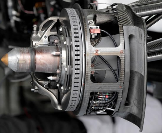
Brake by wire system of a Formula One race car
Image Source: https://www.formula1-dictionary.net

Revolutionizing the braking system for electric vehicles

As electrification takes hold and traditional internal combustion engines are phased out mechanical components, such as the vacuum servo, no longer have a ready power-source, which means electrically driven pumps and motors have to be developed to drive the control systems.

Furthermore to integrate automated driving systems, controls are rapidly moving to electric/ electronic (E/ E) architecture, often loosely referred to as ‘X by wire’ controls.

But, for a brake by wire system to function safely and effectively the integrity of the human machine interface (HMI) needs to be retained as is. And in order to achieve this engineers need to map out the two sets of forces (In this case measured in force/ area, or pressure): The pedal effort applied by the driver, and the resultant pressure on the caliper pistons/ wheel cylinders in the ‘traditional’ hydro mechanical system.

 Only high quality pressure sensors will do

The integrity of this data is crucial to the effective development of the E/ E system, so only high quality pressure sensors, that are capable of accurate and repeatable recordings, can be used.

Not only must these sensors be capable of capturing highly accurate data, but they need to do this in an environment where harsh chemicals, heat, vibration and space constraints do not always favor carefully calibrated measuring equipment.

For this reason development teams rely on a handful of quality pressure sensor suppliers to provide measuring equipment they can rely on.

It’s all about the feel

Armed with the input vs. output pressures engineers now need to try and replicate, not so much the outright stopping performance, but the feel of the traditional system. Using wheel speed sensors it is quite easy to maximize retardation, but it’s not that easy to replicate the drivers’ feel when carrying out very light ‘check braking’ at low speeds.

This is where the real world data is worth gold: The pedal effort vs. system pressure needs to be replicated by an electronic control unit which manages the rate at which the brakes are applied. This in itself is a mammoth task, as drivers apply the brakes at different rates depending on road and traffic conditions and personal preference: A driver in a hurry may leave braking to the last minute and have to brake harshly, whereas elderly people may expect a far more leisurely event.

The degree of difficulty in achieving this driver feedback can be gauged by the performance of the system when fitted to Formula One race cars: After three years there are still teams that are unable to provide the driver with a brake by wire system that provides enough feel for them to commit to heavy braking maneuvers.

So while brake by wire systems may still be a few years away from series production in mass volume, cost sensitive vehicles, brake system specialists have been able to accurately quantify, with the aid of pressure sensors, exactly what is required.

Subscribe To Our Newsletter

Join our mailing list to receive the latest news and updates from our team.

You have Successfully Subscribed!