Test fixture pressure sensors – Pressure measurement in the aircraft engine compartment

Test fixture pressure sensors – Pressure measurement in the aircraft engine compartment

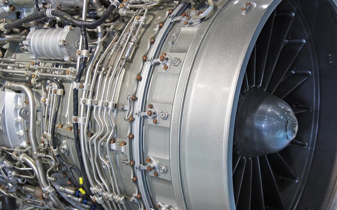
As many engineers have found to their chagrin, dealing with pressure measurements in the engine compartment of an aircraft can be a delicate and frustrating experience. The heat, vibrations, orientation, and a multitude of other factors come into play. So how can we hope to develop a method for consistent and accurate readings? Well naturally, we’re left with hours, days, and most likely months of testing! However, we still need a test sensor that can rise to the occasion, function through all these changing conditions, and continually produce correct and repeatable results. We are engineers after all, and repeatable results are an occupational necessity. Thankfully for us, STS has stepped up to the plate to provide a complete series of pressure sensors to meet all of our testing needs. Where those needs can range from specific temperature requirements, size constraints, sealing material, and electrical output signals. All of these requirements will be covered in the following article as we address STS pressure transmitter usage for our testing needs.

Continuing with our engine compartment example, let’s zero in on the oil pressure. One of the first concerns while selecting a pressure sensor for this test is temperature resistance. Naturally, it gets quite warm next to an aircraft engine; therefore, we must ask ourselves, can the sensor be mounted alone or does it need a heat shield? More importantly, will the sensor even function properly when the components begin to heat up? Erratic oil pressure readings are very low on the wish list for a pilot! Therefore, both are valid points; but don’t fret too much. The STS line of pressure sensors include excellent temperature resistance, up to 125° C. This, in most cases, takes care of our initial temperature concerns and allows the sensor to be mounted it the most logical position in the engine compartment without the need to worry about temperature interference. Furthermore, we can fiddle, finagle, and fine-tune the test sensor’s location without constantly looking over our shoulder to see if the increased temperature will manipulate our results.  This provides us with a great deal of flexibility when constructing our test plan. 

Along the same subject of mounting locations, the size of the sensor is also crucial. Trying to wedge an ungainly box next to your sleek engine for a series of oil pressure tests would undoubtedly result in a few raised eyebrows amongst all those concerned. Additionally, space in this area is constantly at a premium. However, that is one bridge you don’t have to cross as STS has produced a very compact and low profile pressure sensor that makes for convenient mounting throughout your testing area of operations. Thanks to the advanced customization options, which we’ll discuss later, the exact dimensions vary from sensor to sensor. However, they tend to fall within the 50-60mm (2.0-2.4”) range. This small size allows for easy fixturing using common Adel clamps or any other off the shelf bracket without spending the time to design a custom mounting scheme, or trying to dream up a new overly complicated fixturing method every time the sensor has to be relocated to find the optimal position for oil pressure readings. All in all, this is certainly a time saver when we are focused on a timely and efficient series of tests.  

The last factor that we’ll touch on that can be invaluable for our pressure testing is customization. More often than not, the pressure sensors that are readily available on the market for such a test have a well-defined scope that they operate in. A single configuration that works best in ‘this’ pressure range, for ‘that’ frequency of collection, and it all comes with just ‘this’ product design. However, STS pressure sensors offer several options and customizations that give us the freedom to not limit our test based on our sensor’s individual capabilities.  

For our example, we of course must have a sealing material that with neither contaminate the oils, nor degrades with constant exposure. Well, we have several options for the sensor seals that can accomplish just that, including EPDM and Viton to ensure that the sensor is operating at peak performance for the entire test. Or, conversely, we can opt for a metallic sealing option to ensure proper test results. What’s more, perhaps we need a frontal diaphragm connection, with a PUR cable, along with 20 mA output signal. STS can deliver exactly that, along with any number of other combinations to ensure that the process connection, electrical and output signals, pressure connection, and seals are exactly what we need. In essence the sensor is cherry picked for our test and not simply some component we need to shoehorn into the test setup.  

To recap, we are required to design a series of oil pressure tests; and as with most tests, many of the factors will be manipulated. The heat, mounting method, pressure range and a mind-numbingly large number of other issues will all be changing constantly over the course of the test. To cap it all off, we need a test pressure transmitter that can fit into this envelope and consistently produce accurate results. Well we can at least nip that problem in the bud straight away by incorporating an STS pressure transmitter for our testing regimen. The high temperature and pressure ranges, combined with custom seals, process connections, electrical and signal outputs, and overall design ensure that this is a sensor that can pre-configured to slide seamlessly into your testing apparatus, and not require that your entire system by reconfigured to suit the sensor.


Cabin Pressure Testing

Cabin Pressure Testing

Proper cabin pressure is crucial in the aerospace industry. After all, a pilot rendered unconscious from lack of oxygen will not be overly helpful at the controls of a complex aircraft. Therefore, it falls to the engineers to develop a stellar cabin pressure system that will withstand even the most extreme conditions. To do that, we will of course be spending a great deal of time at the bench testing and re-testing every manifold, valve, and pressure vessel. So what do we need to create an effective and resilient cabin pressurization system? An effective and resilient pressure transmitter of course! In the following article we will cover many of the possible options and applications of the STS pressure sensors and how we can use them in this situation.

As we piece together our master plan for the cabin pressure test we will want to focus our attention on two critical factors; temperature resistance and overall accuracy. For our example, let’s move forward with a turbofan aircraft. As the air enters the engine, it is compressed by a series of rotors and a portion of this compressed air is diverted towards the cabin air system for the pressurization process. Now is the time to remember the compressible flow equations. As the incoming air is compressed, the temperature will also increase very quickly. Immediately after this initial compression the cabin air is transferred to a preliminary intercooler to shed a certain amount of that heat to the ambient air.  

As you can imagine, there is a great deal heat going into this area of our system. So naturally, if we wish to install a test pressure transmitter in this space to fine-tune, or verify, our cabin pressurization process, we’ll need one that includes an exceptionally high temperature resistance. Well, the STS line of pressure sensors offers us just that with a temperature limit of 150˚ C (302°F), where the sensor will continue to the function and transmit accurate data even in these  warm conditions. Furthermore, STS has adapted a fully customizable and modular approach to their design process to give us access to many more features in addition to superb temperature tolerance.  

Once the pressurized air has been cooled sufficiently, and its pressure recorded by our test sensor, the air can proceed to the primary manifold where the still warm air is mixed with colder atmospheric air to achieve a comfortable environment for the pilot. This is yet another crucial link in our cabin pressurization process, and it is therefore very likely to be equipped with a test sensor throughout the course of system testing. However, the conditions here are vastly different from those seen in the intercooler. Will the same pressure sensor even work here? The answer from STS is, YES! The wonderfully adaptable modular approach to the STS line of pressure sensors ensures that we will always be able to order a sensor to fit our needs.  

For our purposes, the manifold is one of the last stops for the air before it is passed along to the cabin. Therefore, accurate pressure measurements are crucial to ensure that the cabin is kept at standard ground level atmospheric pressure. With that in mind, we have the capability to select the most accurate variation of the sensor at ≤± 0.05% FS. This highly precise transmitter, the ATM.1ST model, will ensure that we the engineers have reliable and consistent data for this particular stage in our cabin pressurization sequence. 

While we’re on the subject of options and modules, STS also gives us the flexibility to select from a long list of possible electrical connectors and output signal types to ensure that each sensor is precisely assembled to our needs. This saves us from the painstaking process of redesigning a test fixture to the sensor’s needs. The standard connectors that we can readily choose from include PUR, FEP, and 5-pin M16 connectors. However, if this is not exactly what we need, STS does have the capacity to work with us to create an entirely custom connector, so there’s nothing to worry about!  

The last stop in our cabin pressure system that could do with a sensor during our testing project is the outflow valve. It is here that excess air is bled off into the atmosphere if we approach the point of over-pressurizing the cabin. Just like a test sensor in the manifold, accuracy is pivotal to ensure that we are maintaining the exact desired pressure in the cabin at all times, so once again the high precision ATM.1ST line would seem a logical starting point.  

Let us briefly reiterate the stops we made along our test plan. First, we have the intercooler which serves a fundamental role as the air moves towards the passenger compartment. Therefore, this location is also fundamental for our testing and requires a sensor that can register highly accurate data while at the same time resisting the high rate of temperature exchange in that particular area. Can the options available to us with the STS sensor accomplish this? Check. Next we moved to the manifold, or air mixing box, where accuracy and consistency are paramount. What’s more, a temperature transmitter would not go amiss in this area. Can we tackle this task through STS? Check. Last stop, the outflow value, where we once again need to precisely measure and record pressure data for our test, and again we can put a big check mark next to STS pressure sensors being able to keep up. All in all, the ATM.1ST pressure sensor has the potential to fulfill all our diverse testing needs throughout a dynamic and complex aircraft system, so stride forward confidently into the world of cabin air pressure!

Selecting your pressure sensor: A how-to guide for the aerospace engineer

Selecting your pressure sensor: A how-to guide for the aerospace engineer

Devising and creating an aircraft is a daunting task, and no small feat by any means. The endless calculations, designing, simulations, and re-designing seems to be a perpetual process; however, we will eventually reach the milestone of intensive testing! This is a very exciting process, all the 3D parts you’ve designed, the systems you’ve pieced together, and all the components are now sitting right in front of you. It is time to prove to yourself, and your managers, that everything will operate flawlessly, but don’t get ahead of yourself! To do that, we need top-notch data recording equipment to verify our system’s performance. What’s more, we need test sensors that can function in the most extreme conditions both inside and outside the aircraft. Well, that is why STS is here, to furnish us with reliable pressure measurement transmitters to ensure that our rounds of pressure testing work just as smoothly as the system we designed. We’ll spend the rest of this article presenting a step by step guide to fully acquaint you with the full range of options that STS offers and how to integrate those into our system.

Accuracy

Step one, we need to take a close look at the aircraft system we’re testing, and determine the precision required for our data collection. For example, the hydraulic system that controls the aircraft’s brakes often operates within a specific pressure range, and this range is large enough that extraordinary precision is not a requirement when selecting a test sensor. Therefore the STS option of ± 0.25% FS would be a suitable option. On the other end of the spectrum, the oil pressure must be monitored much more judiciously when compared to the brake hydraulics. With that in mind, we can select the STS option for a high precision pressure transmitter with the highest degree of accuracy available, namely ± 0.05% FS to ensure that the oil pressure remains at its peak level throughout the engine system. 

Temperature  

Now that we’ve established the required accuracy for our application, let’s move on to integrating the pressure sensor into our test aircraft system. Naturally, the pressure oriented systems on an aircraft are exceptionally diverse in terms of size, operating temperature, and pressure medium; consequently, we need the freedom to cherry-pick every one of these features for our sensor. 

For the next step in the selection process, let us turn our attention to the operating temperature. In an aircraft, your test pressure sensor could potentially be recording data within the sweltering confines of the engine compartment. Conversely, it could be located externally, measuring the Pitot pressure or perhaps the de-icing fluid pressure in which case the operating temperature will be drastically lower than the engine compartment. Never fear, STS offers an impressive range of operating temperatures from -25 to 125° C. This base range will by and large cover the majority of our aerospace pressure needs. To sweeten the deal, all STS sensors are manufactured to include a compensated temperature range, meaning the inherent measurement error is drastically lower within the limits specified above. This is an exceptionally beneficial feature when completing intensive testing on our pressure systems! 

The aforementioned temperature range is by no means set in stone. When the need arises, we can opt to have our sensor outfitted with cooling fins to boost to max temperature to 150° C. Such a need might arise if the sensor was to be located next to the engine exhaust system which can radiate a significantly large amount of heat. Furthermore, we can choose for our sensor’s minimum temperature to be lowered -40° C if the sensor was to be exposed to a particularly high altitude. That covers the selection process for your sensor’s temperature resistance; always keep your operating environment in mind!

Process Connection

As previously mentioned, the sizes and gauges of the different pressure systems within an aircraft are far from constant. Therefore, the next step in our selection process is to determine the optimal location for the sensor, and select a connector that will allow the sensor to fit in that particular location. For example, take an aircraft brake system. The hydraulic system will consist of various tube sizes and components, but once you have selected the exact location for your sensor, the process connection can be chosen. STS offers a range of sizes and diaphragms including G ¼ M and G ½ M with the additional choice for Hastelloy and frontal diaphragms, amongst other choices. This wide range of possible selections ensures that we can order a sensor that will slide into our test system perfect without any special retrofitting in order to install, which lowers the workload for us!  

Seals 

The final major component of our test sensor that we’ll cover is the sealing materials that are available to us. As with the process connector, the material to select to seal your sensor is highly dependent on the fluid that makes up your pressure system. Luckily for us in the aerospace field, our pressure systems will seldom experience corrosive, acidic, or other unsavory fluids. Nevertheless, we still must give some thought to our seals. In the case of our hydraulic system for landing gear, the standard choice is Nitrile (NBR) as our seal. This rubber-like material is ideally suited for this application in addition to being resistant to oils and other lubrication materials. However, if we’re expecting high temperatures or other harsh conditions that are present in an engine compartment then Viton would be a much more suitable choice with its improved temperature resistance and durability. Last but not least, EPDM rubber has a proven track record when dealing with brake fluids. These are only three of the many sealing options that STS offers, with the main takeaway being that not all seals are interchangeable. Research your system, the options available, and make the best choice to ensure optimal sensor results! 


Now you are fully prepared to begin the pressure sensor selection process for your aerospace testing! We’ve covered the level of accuracy required for your sensor, which is dependent on the exact system in which the sensor is located. We then moved on to determining the correct level of temperature resistance required for our individual applications. Followed by the process connection where we can select various sizes and diaphragms to ensure that the sensor is always tailored to our exact needs. Our last point was to explain the primary differences between the many seal options that are available to you, and the ideal application of each one. With this information, you can look at the primary components of your test pressure sensor and make the best selections to ensure that your sensor is quite literally made just for your use!

Mapping boost pressure on downsized turbo engines is the key to success

Mapping boost pressure on downsized turbo engines is the key to success

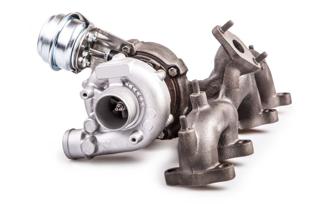
To meet ever tightening emissions legislation across the world OEMs are turning to downsized Spark Ignition engines. While these smaller engines consume less fuel and produce significantly lower emissions they require forced induction to deliver the performance drivers have come to expect from modern passenger vehicles.

The driveability of these downsized turbo engines must at least equal the performance of their naturally aspirated equivalents. This requires full boost pressure at low engine speeds without running out of steam at high speed, which can only be achieved with a sophisticated boost pressure control system.

The main problem with these forced induction spark ignition engines is the precise control of the air-fuel ratio near stoichiometric values at different boost pressures. At low speeds, these engines are prone to knock under medium to high loads.

Modern pressure control systems

Controlling the turbine-side bypass is the simplest form of boost pressure control.

Once a specific boost pressure is achieved, part of the exhaust gas flow is redirected around the turbine via a bypass. A spring-loaded diaphragm usually operates the wastegate which opens or closes the bypass in response to the boost pressure.

In recent times manufacturers have turned to variable turbine geometry to regulate boost pressure. This variable geometry allows the turbine flow cross-section to be varied to match the engine operating parameters.

At low engine speeds, the flow cross-section is reduced by closing the guide vanes. The boost pressure and hence the engine torque increases as a result of the higher pressure drop between turbine inlet and outlet. During acceleration from low speeds the vanes open and adapt to the corresponding engine requirements.

By regulating the turbine flow cross-section for each operating point the exhaust gas energy can be optimised, and as a result the efficiency of the turbocharger and therefore that of the engine is higher than that achieved with bypass control.

Today, electronic boost pressure regulation systems are increasingly used in modern Spark Ignition petrol engines. When compared with purely pneumatic control, which can only function as a full-load pressure limiter, a flexible boost pressure control allows an optimal part-load boost pressure setting.

The operation of the flap, or vanes, is subjected to a modulated control pressure instead of full boost pressure, using various parameters such as charge temperature, ignition timing advance and fuel quality.

Simulation reduces time to production and development costs

Faced with a plethora of complex variables, manufacturers have turned to simulation during the design and test phase.

A significant hurdle to overcome with downsized turbocharged engines is the narrow range within which the centrifugal compressor operates stably at high boost pressures.

The only way to build an effective simulation model is through extensive real world testing. This testing is mostly carried out on engine dynamometers in climatic chambers.

During wide open, and part throttle, runs the following pressure information is recorded:

  • Intake manifold pressure
  • Boost pressure
  • Barometric pressure

Of course this is all integrated with engine temperatures (Coolant and oil) to gain a picture of engine performance over the full engine speed range.

During this testing it’s important that engineers note any abnormalities in performance, as events such as exhaust pulses at specific engine speed can set up standing waves which can excite the impeller at a critical frequency which will reduce the life of the turbo, or even lead to catastrophic failure.

Therefore the measurement of pressure performance maps of both compressor and turbine is vital for the creation of an accurate extrapolation model for implementation during simulation.

A well-developed simulation tool can save the OEM time and money in dynamometer and road tests, but can only be developed once the pressure maps have been completed.

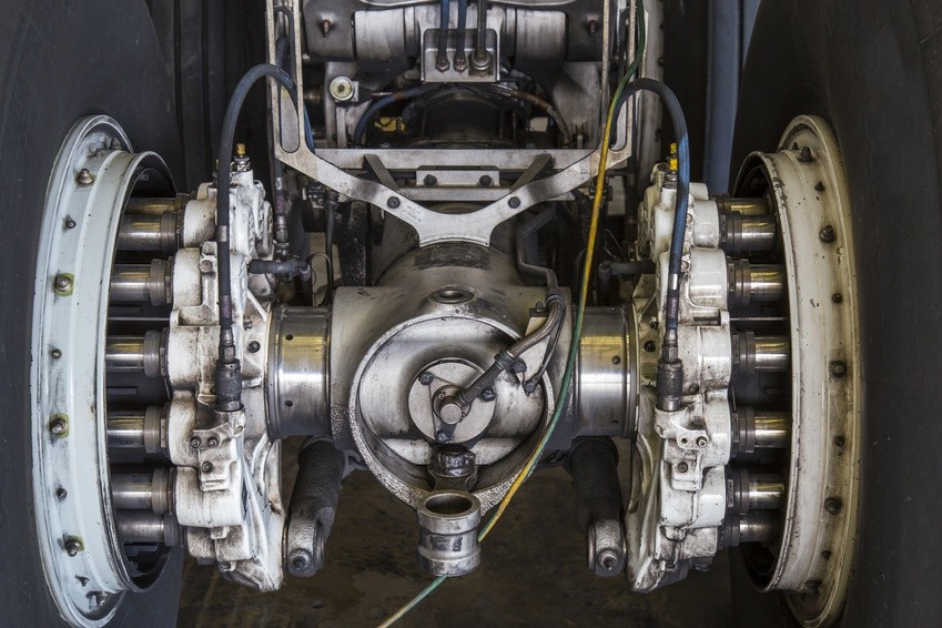
Landing gear hydraulic pressure testing

Landing gear hydraulic pressure testing

Imagine, you’re a pilot in your own plane, cruising on a beautiful day. You line up your approach to the airstrip and flip the switch to actuate the hydraulics for the landing gear to deploy. Suddenly, a low pressure warning appears and the landing gear won’t deploy. Now you have a problem! Amongst the grumblings under your breath will likely be a few unsavory comments about the engineers that designed that hydraulics system. Well, that’s us; and that pilot we’re imaging, that’s our client. They deserve to have a reliable and flawless landing, don’t they? Therefore, it’s on us to design a hydraulic system that can achieve just that, but how? Well the specifics, components, and design are across the board from plane to plane; however, there is one point that is guaranteed to be universal for our endeavors, hydraulic pressure testing! We will all test and test, then try to damage the system and test again! So naturally, we need a pressure sensor that can consistently and accurately record the conditions in our hydraulics system as we fine-tune all the details. Well we have a sensor that can do exactly that and for the remainder of this article we will explore the capabilities of the STS high precision pressure transmitter ATM.1ST.

As we begin to develop our hydraulic pressure measurement regimen, we must first determine the exact data we wish to collect. As we all know, ‘pressure’ is a very broad term to use in a hydraulic system and has very little meaning on its own. Are we referring to the accumulator pressure, pump delivery pressure, the regulator pressure, or perhaps the relief pressure? That decision is up to you, but thankfully STS has developed a series of pressure transmitters that can collect data in any of these sub-components. What do we mean by that? Well, the STS high-precision pressure transmitter ATM.1ST is designed with a modular and adaptable approach. We, as the engineers, can cherry-pick the features and capabilities for every sub-component of the sensor to ensure that every last one is perfectly suited for the environment that it will encounter over the course of the test.  

Let us now break down these sensor modules for a moment. First, we have our choice of materials for nearly every part of the sensor to ensure strength and durability. For example, the housing and transducer can be constructed from stainless steel or titanium depending on the burst pressure we must withstand amongst other factors, and this will in turn be determined from your particular hydraulic setup.  

However, our material selection is not limited to the housing. We also have the power to pick and choose the seal material for our sensor. The selections in this department include Viton, EPDM, Kalrez, and NBR. Naturally, the hydraulic fluid will be consistent throughout the landing gear system; therefore, once we determine the seal material that will have the best interaction with the fluid that particular material can be guaranteed to function throughout the system. Another factor to be kept consistent throughout our test setup is the overall accuracy of our pressure sensors. Luckily, STS grants us leverage over that characteristic as well with the high precision sensors of the ATM.1ST line. We have 0.25%, 0.1%, and 0.05% FS to ensure that our data collection is both accurate and consistent throughout the entirety of the test.  

The last two modular selections that are prudent to our landing gear testing are the electrical and process connections. In the electrical world we have FEP, PUR, and PE cables to select from, along with a range of different connectors. As for process connections, our diaphragm, DIN, and other specifications are entirely at our discretion. While the sheer volume of different combinations may seem slightly overwhelming at face value, they grant us the capability to piece together a pressure sensor that will slide into our test setup seamlessly without driving any special setup or design changes.  

Now let us return to our landing gear testing. As we develop and test the hydraulic system to achieve flawless landing gear operation we are going to need data from several locations within the system. As mentioned above, we have the accumulator that acts as a damping device of sorts to smooth out any pressure variations within the system. Naturally, we as the engineers need to know what those variations are exactly. Therefore this seems to be a perfect location for a test sensor!  

On the subject of pressure maintenance, the regulator also falls squarely into this category. As the pressure fluctuates due to valves opening and closing or any irregularities in the system, the regulator kicks in to ensure that the system pressure remains within the specified range. Once again, this is another crucial component to keep an eye on as we develop our landing gear, and we now have the resources to select a perfectly customized pressure sensor to slide into the system and accomplish just that with precise measurements and easy to install electrical connectors. 

In review, we are tasked to develop a reliable landing gear system via a rigorous curriculum of testing. However, the hydraulic system of such a mechanism is extremely diverse in terms of components and potential locations for sensors. Thankfully for us, STS has produced a reliable little powerhouse in the ATM.1ST pressure sensor that allows us to have nearly complete jurisdiction over all aspects of the sensor; including materials, accuracy, sealing, and electrical connectors. Long story short ladies and gentlemen, this high-accuracy sensor allows us to devise a streamlined and robust testing process where our test sensors complement our setup, and do not dictate it.

Subscribe To Our Newsletter

Join our mailing list to receive the latest news and updates from our team.

You have Successfully Subscribed!