Pressure measurement in test & measurement applications demands a robust core technology

Pressure measurement in test & measurement applications demands a robust core technology

Whether on engine and transmission test beds, the monitoring of hydraulic systems, leak testing or the calibration of medical devices, users must be able to rely upon the precision of their pressure measurement technology.

Reliable pressure measurement technology demands a robust core technology. Although there are different types of pressure transmitters, measuring instruments using piezoresistive semiconductor technology are often the first choice for test & measurement applications. The simple reason for this is that, in contrast to thick-film sensors (ceramic base material) or thin-film sensors (metal base material), piezoresistive pressure sensors based on semiconductor  are characterized by an unrivalled sensitivity, which makes pressures even in the mbar range measurable. Complemented by an outstanding precision of up to 0.05 percent of span, piezoresistive pressure sensors provide exactly those properties essential to calibration tasks in the medical field or the demanding requirements of engine development.

Long-term stability even under overload

Especially in the testing of new technologies, users cannot know in advance which pressures their sensors will encounter. Particularly when measuring pressures in fluid pumps or hydraulic systems, pressure peaks can occur that far exceed the targeted measurement range. If users in this case have not acquired their pressure transmitters on demand, a defective measuring device can throw development cycles way off course – and do so with far-reaching consequences.

Besides high precision, the lifetime optimization of measuring devices is a further factor that demands a robust core technology for test & measurement purposes. This requires a thorough examination of the base materials and a conscientious qualification of the products on the part of the manufacturer. Temperature susceptibility, for example, is a weakness of piezoresistive pressure transducers, which can be compensated for by various measures to the extent that it no longer plays a significant role in practice (read more on this topic here).

Total error – Highest precision over the entire temperature range.

Two further important measures on the manufacturer’s side, implemented as standard by STS, also contribute to optimizing the service life of pressure transmitters. In piezoresistive pressure sensors, there still exists quite a lot of movement, especially during their first year of use. Thermal treatment, however, can be employed in anticipation of this trait, now stabilizing the measuring device accordingly. Those errors common in the first “year of life” of a sensor have thus been eliminated. Furthermore, it is now standard for STS pressure transmitters to withstand at least three times their measurement range in overload pressure, without even suffering any damage. This overpressure, incidentally, can be individually designed in according to customer requirements. Read more about the lifetime optimization of pressure transmitters here. 

Test & measurement: Precision is individual

When is a pressure transmitter deemed precise? Quite clearly, when it meets the requirements of the respective application as exactly as possible. This means that the more individually a measuring device can be adapted to an application, the more accurate the measured results it can deliver.

The serving of application-specific requirements is particularly important in test & measurement applications. Precision, of course, also plays a role here, since a pressure sensor optimized for a measurement range of 1 to 5 bar is more accurate at an error of 0.05 % of span than a device with a measuring range of 1 to 50 bar. Often, however, integration of the measuring device often plays an important role also. In the development of new engines, for example, so many sensors are mounted on the test bed that connection options play just as important a role as the dimensions of the measuring device itself.

As a rule, STS always works to a modular design principle when developing its measuring instruments. This means that all products can be supplied with any process connection as required. A wide range of materials is also available to rule out any eventual media incompatibilities. Pressure measurement ranges can likewise be individually optimized to the respective requirement. And all of this individualization of our measurement devices can be realized within the shortest of timeframes. This is an important criterion for test & measurement purposes, since unexpected measurement requirements can arise, especially when testing out new technologies. To avoid long downtimes and unnecessary financial losses, the delivery of a solution that meets all of the specifications thus becomes an essential factor in itself.

The right sealing solution for every application

The right sealing solution for every application

In order to maintain the performance of piezoresistive pressure sensors and optimally protect them in harsh conditions, various sealing options should be taken into consideration. STS offers several solutions here, which are selected according to the given requirements and the actual application environments.

A sealing ring, or O-ring, is used in most standard applications. This common sealing method is very flexible and highly versatile. STS offers sealing rings in many different product variants, where the specific material is selected according to the pressurized medium.

Should the seal be exposed to aggressive media or extreme temperature conditions, sealing with a simple ring then becomes insufficient. The elastomers commonly used in the manufacture of O-rings become porous when exposed, for example, to media containing hydrocarbons. Problems can also arise during decompression, where a steep pressure drop may even rupture the sealing ring.

A common alternative to the simple sealing ring is a welded seal, where the measuring cell and pressure connection are welded directly together. This type of seal is somewhat more stable, but, just like the O-ring, can only withstand a maximum pressure of 250 bar/3600 psi. Up to this value, the O-ring and welded seal would complement one another, depending on the application environment and the predominant medium. With an aggressive pressure medium like gasoline, for example, only the welded seal would be suitable, whereas in saltwater, an O-ring should be strictly used to prevent corrosion of the seal.

Overview of the various sealing solutions

As soon as the limit value of 250 bar is exceeded, only a metal seal can then be used. At STS, this elastomer-free metal seal is therefore offered for application environments at very high pressures. Because of its properties, this sealing solution can also withstand exceptional conditions and extreme exposure to corrosive chemicals, vacuums and intense radiation exposure.

Practical use of sealing solutions

A large company that manufactures grinding and compressor systems for various industries relies mainly on the pressure sensors offered by STS, for which there is a wide range of sealing rings. Here the temperature conditions, as well as the nature and compatibility of the media, are known in advance, so that these can be easily validated before use and the sealing rings manufactured accordingly.

For another customer who manufactures test beds for the automotive industry, the material involved and the temperature conditions encountered are only lastly determined by the end user. The essential properties of the sealing solution therefore depend upon these subsequent specifications. The seals used here must therefore ensure from the outset a high degree of flexibility, meaning that our robust welded seals form the choice here.

Media compatibility of piezoresistive pressure transmitters

Media compatibility of piezoresistive pressure transmitters

In selecting the right pressure transmitter for individual applications, there are numerous criteria that must be considered besides the pressure range to be measured and the extant thermal conditions. Among these falls the subject of media compatibility: The housing and process connection must withstand the environmental conditions, so that the sensor can perform its service over the longer term.


Material selection therefore follows two important considerations: On the one hand, that there is a chemical tolerance to the contact media. The other factor is that preventative considerations also play an important role. It should not only be clarified whether the pressure transmitter will remain functional longer term. It must also be established whether the materials used in the pressure transmitter itself can lead to dangers when coming into contact with particular substances – the pharmaceuticals industry would be an obvious example here. In the following, we will be showing which media incompatibilities occur with which materials and what the solutions to this might be.

Chemical-physical media compatibility with sealant material & cable

It is not only the housing material itself that should be included in considerations of media compatibility. Other elements of the pressure sensor also come into contact with the surrounding or process media and these materials are to be particularly contemplated.

The majority of pressure transmitters come with a sealant made of elastomer. The problem here is that the elastomer can dissolve when it comes into contact with aggressive media such as biodiesel, for example. In this case, a front-flush, welded and elastomer-free sensor should be employed.

One further factor is the cable that serves in transmitting the measurement data. We will adopt the example here of using a submersible probe in a swimming pool. For reasons of hygiene, swimming pools use chlorinated water. As standard, submersible probes use PE or PUR cables. Although chlorinated water alone presents no issue to these cables, the chlorine vapor rising from this water does do, since this is much more aggressive than the water itself. These cables, over a period of time, will become porous above the water level (visible as a white discoloration) and water will then penetrate within. Subsequently, the sensor itself will also fail. For this reason, teflon cables would be used in such an instance.

Chemical-physical media compatibility with housings

Viscous media

With viscous media, using paints as an example, deposits within the sealant channel can be a consequence. To prevent contamination, smooth membranes free of any dead space and without an open pressure channel are needed for such applications, so that the sensor can be cleaned free of all residues.

Abrasive media

When pressure transducers come into contact with abrasive media such as concrete, a simple membrane of stainless steel provides insufficient protection. In this case, a membrane coated with Vulkollan® foil will be required.

Galvanic & acidic liquids

A chromed pressure sensor may look better from an aesthetic viewpoint, but in practical terms it is anything else. When a pressure gauge with a metal housing is used in an electroplating bath, over time only a clump of non-functional chrome will remain. Even acidic fluids, such as sulfuric acid, will react with metals. For this reason, plastic housings are deployed for galvanic and acidic liquids. The most popular solution here being PVDF.

Image 1: Destroyed pressure transmitter due to incorrect material selection

Seawater

Salt water (depending on its salinity) causes long-term pitting to stainless steel housings. This is why most submersible sensors and level sensors are also available in a titanium version.

Open waters / lightning protection

Lightning strikes cannot perhaps be described as a medium, but we will nevertheless look into this a little further. Should a strike hit a sensor directly, then no lightning protection at all will be of any use. Surge protection, however, can be recommended for submersible probes that are used in open waters. An excess voltage and damage to the measuring instrument by a lightning strike in the immediate vicinity can thus be prevented. This is particularly advisable when long-term measuring in remote places is being conducted. The replacement of a defective device here would then be much more expensive than surge protection itself might be.

Preventative media compatibility

The silicon chip of a piezoresistive pressure transducer is surrounded by a transmission fluid. A usual choice here is silicone oil. Although this fluid does not normally come into contact with the surrounding media, some things must nevertheless be observed here – since a defective housing, after all, cannot be totally ruled out. Depending upon application, this could lead to serious consequences.

Heavily oxidizing gases and fluids

When oxidizing gases and fluids come into contact with oils or greases, the threat of explosion then arises. All components exposed to the medium here must be free from oil and grease, and, in preventive terms, the transmission fluid also.

Foodstuffs and pharmaceuticals industries

In this case, the silicone oil must be replaced with a food-safe oil to rule out any contaminations either harmful to health or that act in other ways. Beer, for example, that has come into contact with silicone oil will no longer foam up, and nobody wants to have that.

Paints

Just one drop of oil can render a whole batch unusable. Here also, an alternative must be found.

The media compatibility of piezoresistive pressure sensors: Summary

The optimal pressure sensor for an individual application is dependent upon many factors. For this reason, a deep understanding on the supplier side of the respective customer application is required. STS always offers its customers a needs-oriented consultation that approaches all aspects in providing a reliable solution within the shortest of timeframes – even for lower device volumes.

Download the free infographic on this tpoic: 

Total error or accuracy?

Total error or accuracy?

The topic of precision is often the main consideration for end users when purchasing a pressure transmitter. A variety of terminology relevant to accuracy is involved, which we have previously explained here. Accuracy, however, is only a partial aspect of another concept, total error, which also appears in the data sheets for pressure transmitters. In the following, we will explain how this designation is to be understood in data sheets and what role it should play in selection of the appropriate pressure sensor.

It can be firstly stated that accuracy does not provide information about the total error. This depends on various factors, such as under which conditions the pressure sensor is actually used. We can see in Figure 1 the three aspects of which total error consists: Adjustable errors, accuracy and thermal effects.

Figure 1: Origins of total error

As we see in the illustration above, the partial aspect of adjustable error consists of the zero point and span errors. The designation ‘adjustable error’ results from the fact that zero point and span errors can each be easily identified and adjusted. These are thus errors that users need not live with and indeed both have already been factory-corrected in pressure sensors of STS manufacture.

Long-term stability, also known as long-term error or long-term drift, is the cause of zero point and span errors during operation. This means that these two adjustable errors may reappear or even “worsen” after prolonged use of the sensor. By means of calibration and subsequent adjustment, this long-term drift can thus be corrected again. Read more about calibration and adjustment here.

Accuracy

The partial aspect of accuracy also appears in data sheets under the term ‘characteristic curve deviation’. This lack of conceptual clarity comes down to the fact that the term “accuracy” itself is not subject to any statutorily defined standard.

The term encompasses the errors of non-linearity, hysteresis (pressure) and non-repeatability (see Figure 2). Non-repeatability describes those deviations observed when a pressure is applied several consecutive times. Hysteresis refers to the fact that the output signals can differ at the exact same pressure when this is approached from a “rising” and “falling” direction. Both of these factors, however, are very minor in piezoresistive pressure transducers.

The biggest influence on accuracy, and thus also on total error, comes down to non-linearity. This is the greatest positive or negative deviation of the characteristic curve from a reference line at increasing and decreasing pressure. Read more on the terminology here.

Figure 2: The greatest difference in the characteristic curve when the pressure to be measured is approached several times is termed non-linearity.

Thermal effects

Temperature fluctuations have an influence on the measured values of a pressure sensor. There is also an effect known as temperature hysteresis. In general, hysteresis describes the deviation of a system when the same measuring point is approached from opposing directions. In the case of temperature hysteresis, this hysteresis describes the difference (error) of the output signal at a certain temperature when that specific temperature is approached from a lower or from a higher temperature. At STS this is typically listed at 25 °C.

More on the thermal characteristics of piezoresistive pressure transducers can be found here.

Figure 3: The typical appearance of thermal effects in pressure transmitters.

Total error or accuracy?

The important question that arises from these various aspects, of course, is what users should pay the most attention to in sensor selection. This will vary on a case-by-case basis. Since the aspect of adjustable errors has already been corrected at the factory, this plays only a subordinate role. In this instance, the sensor should in general be recalibrated and adjusted after one year of use.

When purchasing a new sensor, the dual aspects of accuracy and thermal effects now become decisive. The key question in this context is, “Do I perform my pressure measurements under controlled conditions?” This means that when users carry out their measurements near the reference temperature during calibration (typically 25 ° C), the thermal effects can essentially be ignored. The total error designation, however, does become important when pressure measurement is performed over a wide range of temperatures.

Lastly, we will look at a data sheet on the ATM.1st piezoresistive pressure transmitter from STS (Figure 4):

Figure 4: Excerpt from a data sheet (ATM.1st)

The technical specifications for the ATM.1st display both accuracy and total error, where the accuracy entries are broken down into their respective pressure ranges. The given values are derived from non-linearity, hysteresis and non-repeatability at room temperature. Users wishing to perform measurements under controlled temperature conditions (room temperature) can therefore orient themselves toward these accuracy values specified.

The total error depicted in the data sheet, on the other hand, does include thermal effects. In addition, total error is supplemented with the entries of “typ.” and “max.”. The first of these describes the typical total error. Not all pressure sensors are absolutely identical and their accuracy can vary slightly. The precision of the sensors correspond to the Gaussian normal distribution. This means that 90% of the measured values over the entire pressure and temperature range of a sensor correspond to the value designated under typical total error. Those remaining measured values are then attributed with maximum total error.  

Download our free infographic on the subject: 

How to select the right pressure sensor?

How to select the right pressure sensor?

Extensive testing is essential in the development of new technology. To achieve reliable results, measurement instruments are required which precisely meet the requirements. We show you which factors play a role here.

Pressure range

An initial indicator in the search for a suitable measurement technology is the pressure range to be measured and whether a measurement of the relative or absolute pressure is anticipated.

Depending upon application, special features have to be considered. Particularly in test and measurement applications, individual measurement ranges are required which standard sensors with ISO pressure ranges cannot deliver. In this case, sensors are needed which display the appropriate pressure range and thus attain the desired precision.

Precision

In engine development for racing cars, the smallest of measured readings are the deciders between victory and defeat on the track. In this case, the utmost in precision is demanded and in specific applications developers will opt for a sensor with ±0.05% FS.

Within this question of precision, the factors of necessity and cost are balanced against one another. The pressure range to be measured is usually a good decision-making aid. If this were extremely broad, then no exceptional precision would be necessary. Those who nevertheless decide for the most precisely available sensors should be aware that this precision comes at a price.

Temperature

The temperature factor in some cases is difficult to determine. Developers are often not exactly aware over which temperature ranges the pressure sensor employed is to deliver its service. Many pressure transmitters from STS , for example, are optimized for operating temperatures from -25°C to 100°C. In this way, the common areas of application are all covered. In principle, all sensors can be optimized and ordered to a special temperature range so that even at temperatures of -40°C or 150°C accurate results can be attained.

Process interfacing

The subject of process interfacing can quickly become an exclusion criterion for developers, since many companies use standardized connections. Even the location where the sensor is to be mounted can be an important factor here.

There are a multitude of optional electrical connections, whether it be M12, DIN, MIL or others, which should also be offered by manufacturers in a variety of lengths and materials.

STS itself provides a broad range of connectors. A multitude of connection options are possible due to the modular construction principle of these measurement instruments.

Output signal

Equally decisive is the question of whether the measured pressure is to be carried as an analog signal or over a digital interface such as Modbus. With an analog signal transmission, the pressure is converted into an analog signal that still needs to be measured. In a digital signal transfer, the value of the measured pressure is directly expressed across an interface.

Space requirements

In various applications, only a little space is available for the mounting of pressure sensors. For this reason, the size of the sensor combined with the available process interfaces can become an important selection criterion. The form of pressure measurement also plays a role here. Piezoresistive pressure sensors are particularly suited to miniaturization. For this reason, STS can offer sensors of only a few millimeters in diameter.

Materials

Where will the sensor be deployed? Which ambient conditions will it encounter? Will it come into contact with steam, gasoline or particular gases? The housing material determines which media the sensor will be exposed to. For applications on the test bench, stainless steel housings are mainly used. Upon contact with saltwater, the material selection shifts to titanium.

A major influence upon the appropriate sensor is also played by the sealant material. The sealing material remains dependent upon the fluid used in the pressure system. Temperatures to be anticipated must also be expressly included during these considerations.

Certifications

When using in particularly dangerous applications, such as the possibility of explosion, certain certifications are essential which supply information about safe operation of the instruments. Within the STS portfolio, there are sensors like the ATM.ECO/IS, which carries the FM, Fmc, IECEx, ATEX certification, whose use is authorized in explosive areas

Delivery period

Long delivery periods can delay prototype testing and ultimately jeopardize product introductions. It should thus be established in advance whether the required sensors are available or what delivery period is to be anticipated for custom production.

Click on the graphic to download it

The right pressure sensor – Summary

Sensors do not necessarily meet all of the required specifications. In some cases, the required sensor from one manufacturer is not available in the company’s standardized connection option. Considerable additional costs could arise in this case. Delivery periods could also be correspondingly delayed.

To make the choice of the right sensor as easy as possible for customers, our pressure measurement instruments are based on a modular principle. This means that all of our pressure sensors can be calibrated to the required temperature range. Our products are also exceptionally flexible in terms of process interfacing, sealant materials and pressure measurement ranges. Due to the modular construction of our measurement technology, it is possible to deliver pressure sensors to the exact required specifications within the shortest of times.

Pressure Sensors – Glossary of Terms


There is a multitude of terms that are commonly used in association with pressure management. These are referenced on the STS datasheets, included in our articles and used throughout the industry in general. While some may be familiar, others might need explanation. In order to provide you with a clear overview, we created a glossary that features all relevant terms.

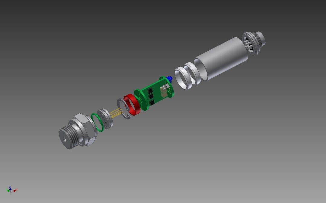
Most important of all surely is the definition of the term “sensor“. This term is used to describe a device which accepts fluid or gas pressures through the process connector and outputs an electrical signal proportional to the pressure. Other words for such a device are transducer or transmitter.

In the following, we provide you with an overview of the most essential, repeatedly used terms. You’ll find all of them sorted in alphabetical order:


A

Absolute Pressure (a)

Pressure measured relative to a perfect vacuum (zero pressure) reference.

Accuracy

There is no single interpretation of accuracy for a pressure sensor. Throughout this glossary there are many terms which relate to potential performance of the sensor generated by the operating conditions. The most common reference to accuracy is that described under Static Accuracy. However, this does not include other features such as Thermal effects, Zero and Span settings and Long Term Stability. The next best accuracy statement is described under Total Error Band.

Ambient Conditions

The condition around the sensor (humidity, temperature, pressure, etc.)

Ambient Pressure

The pressure of the medium surrounding the sensor.

Ambient Temperature

The average or mean temperature of the surrounding air which comes in contact with the equipment and instrument under test.

Amplifier

An electronic device which increases the output signal from the sensor to a higher level. For example, mV to Volts.

Analog Output

A voltage or current signal that is a continuous function of the measured parameter. For example, 0-5 Vdc, 4-20 mA.

ANSI

American National Standards Institute

ASTM

American Society for testing and materials.


B

Background noise

The total noise from all sources of interference in a measurement system independent of the presence of a data signal.

Best Fit Straight Line (BFSL)

The straight line fitted through a set of points which minimizes the sum of the square of the deviations of each of the points from the straight line (‘least-squares’ method). See also Pressure Non-Linearity.

Bit

A bit, or binary digit, which represents a single item of high/low, yes/no, or on/off information.

Breakdown Voltage

The AC or DC voltage, which can be applied across the insulation portion of a sensor without arcing or conduction above a specific current value.

Bridge Resistance

The Input Impedance of an uncompensated unamplified analog output product.

BTU

British Thermal Unit. The quantity of thermal energy required to rise one pound of water 1°F at or near its maximum density (39.1°F) (1055J).

Burst Pressure

The maximum pressure that may be applied to any port of the product without causing escape of pressure media. The product should not be expected to function after exposure to any pressure beyond the burst pressure. See also Proof Pressure (Overpressure).

Byte

A byte is a set of 8 bits, which is treated as an entity. Most computers handle data bits as bytes because it is a power of two. A byte with parity is a 9 bit used for error detection.


C

 Calibration

(1) A test during which known values of pressure are applied to the sensor and corresponding output readings are recorded under specified conditions.

(2) The matching of a pressure controller or indicator to the characteristics of a specific sensor.

Calibration Cycle

The period of time between calibrations.

Centigrade

A temperature scale defined by 0°C at the ice point and 100°C at the boiling point of water at sea level.

Checksum

A checksum is an additional byte or bytes of data appended to a message group containing the arithmetic sum of all previous bytes. In HART communications, the checksum is truncated to the single least significant byte.

Common Mode Pressure

The applied ‘line’ or ‘static’ pressure which is common to both ports of a Differential Pressure Sensor.

Common Mode Pressure Maximum

The maximum pressure that can be applied simultaneously to both ports of a Differential Pressure Sensor without causing changes in specified performance.

Common Mode Voltage

The voltage between each of the output terminals of a differential output product and electrical ground.

Compensation

The signal conditioning used to create a calibrated product to achieve the published specification.

Compensated Temperature Range

The temperature range (or ranges) over which the product will produce an output proportional to pressure within the published specifications.

Compound Range Pressure Sensor

Product for measuring Gage pressures both above and below atmospheric pressure. Typically the Minimum Operating Pressure (Pmin.) is set to -1 bar (-14.5 psi) below atmospheric pressure.

Configuration

The process of setting parameters, values and data which will determine how a sensor will perform.

Current Loop

A two-wire loop in which the current through the wires is maintained according to a controlling device, usually a two-wire sensor. The advantages of a current loop are longer distance signal transmission, better noise immunity, and the ability to power the two-wire sensor throughout the same two wires. The most common current loop is 4 to 20 mA.


D

Damping

See Filter (Electronic) or Snubber (Pneumatic)

DC

Direct Current

Dead Volume

The open volume inside the sensor which is occupied by fluids or gasses being sensed. Does not include the flow channel for flow applications.

Differential Pressure (d)

Pressure difference measured between two pressure sources.

Differential Pressure Sensor

Product whose output is proportional to the difference between pressure applied to each of the pressure ports. Often used to measure flow either side of an orifice plate.

Digital Output

The output signal from a sensor in digital format. For example, RS485, CAN, HART, etc.

Drift

An undesired change that takes place in a pressure sensor over time. It generally only effects the zero and span. This is not to be confused with the thermal effects of the sensor which is often incorrectly referred to as drift.


E

End Point

The pressure output of the sensor at the range extremes. Normally zero and Full Scale but in some cases zero can be offset – see compound range.

Environmental Conditions

All conditions to which a sensor may be exposed during shipping, storage, handling, and operation.

Error (Error Band)

See Total Error Band

Excitation

The supply voltage to the sensor.


F

Fahrenheit

A temperature scale defined by 32°F at the ice point and 212°F at the boiling point of water at sea level.

Filter (Electrical)

A device to sort desired result from undesired. Electrically, a selective circuit which passes through certain frequencies, while attenuating or reject others.

Filter (Pneumatic)

See Snubber

FM Approved

A sensor that meets a specific set of requirements established by the Factory Mutual Research Corporation which sets industrial safety standards.

Full Bridge

See Wheatstone Bridge

Full Scale

The output from a sensor at the specified full scale pressure range. This is not to be confused with span. See span.


G

Gage Pressure (g)

Pressure measured relative to the local ambient (atmospheric/barometric) pressure. Also known as ‘Gauge’.

Gage Pressure Sensor

Product whose output is proportional to difference between applied pressure and local ambient (atmospheric) pressure. Typically the Minimum Operating Pressure (Pmin.) is set to atmospheric pressure.

Gain

The ratio of the change in output to the change in input, which creates it.

Ground

The reference point of an electrical system, or alternatively, the local earth potential (earth ground).


H

Half Bridge

See Wheatstone Bridge

HART Protocol

Highway Addressable Remote Transducer (a digital protocol).

Heat

Thermal energy, expressed in units of calories or Btu`s.

Hysteresis

Deviation in output within the sensor range from ascending to descending for both pressure and temperature.


I

Input Impedance

The electrical impedance measured across the input terminals of the product (as presented to the excitation source, with the output terminals open-circuited).

Insulation Resistance

The resistance measured between specified insulated portions of a sensor when a specific DC voltage is applied at room conditions.

Intrinsically Safe

An sensor which has been installed such that it will not produce any spark or thermal effect, under normal or abnormal conditions, that will ignite a specified gas mixture.

ISO

International Organization for Standardization. A worldwide federation of national standards bodies from some 140 countries.


J

Jumpers

Wire links that allow for changes to be made in input and output sensor configurations.


K

Kelvin

The units of absolute or thermodynamic temperature scale based upon the Celsius (centigrade) scale with 100 units between the ice point and boiling point of water. 0°C = 273.16K (there is no degree [°] symbol used with the Kelvin scale).


L

Linearity

The maximum deviation of the sensor output from a defined straight line during increasing pressure in a calibration cycle. See Accuracy.

Long Term Stability

This is generally quoted as the annual stability and is a combination of the sensitivity and Zero drift over 12 months.

Long Term

Stability is extremely subjective and is dependent upon the changes of environmental conditions, but based on a benign at room temperature.


Measurand

A physical quantity, property or condition which is measured. The term measurand is preferred to “input”, “parameter to be measured”, “physical phenomenon”, “stimulus”, and/or “variable.

Mounting Error

The error resultant from installing the pressure sensor, both electrical and mechanical.


NEMA

The National Electrical Manufacturers Association, which defines enclosures for indoor or outdoor use primarily to provide a degree of protection against dust, rain, and/or splashing water.

NIST

National Institute of Standards and Technology. The US reference for all pressure measurement standards.

Noise

An unwanted signal which can contribute to errors in measurement. Examples are hum (power lines), radio frequency interference (RFI), electromagnetic interference (EMI), and broadband or white noise.

Normally Closed (NC)

The state of a switching device (relay or SSR) whose non-powered state is connected.

Normally Open (NO)

The state of a switching device (relay or SSR) whose non-powered state provides no connection.


O

Offset

The output signal obtained when the Reference Pressure is applied to the pressure port. Also known as “null” or “zero”.

Offset Error

The maximum deviation in measured Offset at Reference Temperature relative to the ideal (or target) Offset as determined from the specification. Often defined as % FS.

Operating Pressure Minimum (Pmin.)

The lower limit of the Operating Pressure Range.

Operating Temperature Range

The temperature range over which the product will produce an output proportional to pressure but may not remain within the specified performance limits. See also Compensated Temperature Range.

Orientation Sensitivity

The maximum change in Offset of the sensor due to a change in position or orientation relative to the Earth’s gravitational field (g).

Output

The electrical signal, which is produced by a pressure applied to the sensor.

Output Impedance

The electrical impedance measured across the output terminals of the product (as presented to an external circuit).

Output Resolution

The smallest difference between output signal readings which can be meaningfully distinguished or resolved.

Overpressure

The Absolute Maximum Rating for pressure which may safely be applied to the product for it to remain in specification once pressure is returned to the Operating Pressure Range. Exposure to higher pressures may cause permanent damage to the sensor. Unless otherwise specified, this applies to all available pressure ports at any temperature within the Operating Temperature Range. Also known as ‘Proof Pressure’. See also Working Pressure.


P

Polarity

Most sensors operate from a Direct Current (DC) supply where the positive and negative connections are specified. Such sensors are generally protected from “reverse” polarity connection.

Position Sensitivity

See Orientation Sensitivity.

Potentiometer

A variable resistor often used to set zero and Full Scale within an analog output sensor.

Power Consumption Maximum

The maximum electrical power consumed in normal operation of the product, dependent upon the Supply Voltage and any internal power saving modes of the product.

Power Supply

A separate unit or part of a circuit that supplies power to the rest of the circuit or to a system including the sensor.

Pressure Hysteresis

The maximum difference between output readings when the same pressure is applied consecutively, under the same operating conditions, with pressure approaching from opposite directions within the specified Operating Pressure Range.

Pressure Non-Linearity

The maximum deviation of sensor output from a straight line fitted to the output measured over the specified Operating Pressure Range. Standard methods of straight line fit specified for this calculation are either B(F)SL, BFSL through Zero (Best FIT Trough Zero) or TSL (End Point). See Total Error Band.

Pressure Range

The pressure values over which a sensor is intended to measure, specified by their upper and lower limits.

Pressure Repeatability

The maximum difference between output readings when the same pressure is applied, under the same environmental conditions, with pressure approaching from the same direction. This is considered short term i.e. measurement taken within a few minutes of the original but still under the same environmental conditions.

Pressure Response Time

Time taken for output of the product to change from 10% to 90% of Full Scale Span in response to a step change in input pressure from the specified Minimum to Maximum Operating Pressure.

Proof Pressure

The maximum amount of pressure that can be applied to a pressure sensor without changing any specification. See maximum pressure. See Overpressure.

PSIA

PSI is the most common measurement of pressure used in North America. It is the measurement of pounds per square inch. (A) absolute pressure is referenced to a vacuum.

PSIG

PSI is the most common measurement of pressure used in North America. It is the measurement of pounds per square inch. (G) Gage pressure is referenced to ambient air pressure.


R

Range

The upper and lower pressure limits that a sensor is required to measure.

Ratiometricity

See Supply Voltage Ratiometricity.

Reference Pressure

The pressure used as a reference (zero) in measuring product performance. Unless otherwise specified, this is vacuum (0 psi a) for an Absolute Pressure Sensor and local ambient atmospheric pressure (0 psi g) for Gage, Compound and Differential Pressure Sensors.

Reference Supply Voltage

The voltage excitation used as a reference in measuring sensor performance. For example 5.00 ±0.01 Vdc.

Reference Temperature

The temperature used as a reference in measuring sensor performance. For example 25 ±3 °C or 75 ±5°F.

Repeatability

See Pressure Repeatability.

Reranging

A procedure allowing the user to reconfigure the sensor to a different range than originally established.

Resolution

See Output Resolution.

RFI

Radio Frequency Interference.

Room Conditions

The ambient conditions used for both the calibration and operation.


S

Sealed Gage

This is a pressure measurement reference to one standard atmosphere which is sealed within the sensor.

Self Heating

Internal heating of a sensor as a result of power dissipation.
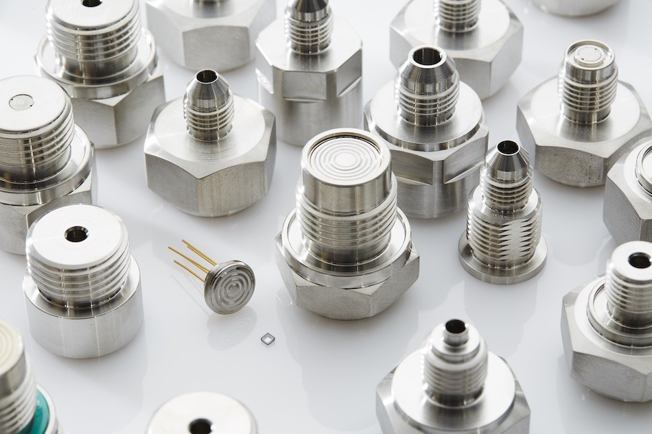
Sensing Element

The part of a sensor, which reacts directly in response to the pressure.

Sensitivity

The ratio of output signal change to the corresponding input pressure change. Sensitivity is determined by computing the ratio of Full Scale Span to the specified Operating Pressure Range. Also known as “Slope”.

Sensor

That component of a transducer or transmitter which converts the fluid or gas pressure into an electrical signal.

Shield

A protective enclosure surrounding a circuit or cable which is to protect it from an electrical disturbance such as noise.

Shift

An ambiguous term sometimes used to describe a permanent change in output of a sensor. The terms ‘Offset Shift’ and ‘Span Shift’ are also sometimes used to describe output changes due to temperature. To avoid confusion, these should be replaced by Thermal Effect on Zero (Offset) and Thermal Effect on Span. See also Drift.

Shunt Calibration/Rcal

A method of generating an electrical output to match the electrical output that would be given in response to an applied pressure. This is accomplished using a resistor to unbalance the bridge electrically rather than with strain introduced by applied pressure. With standardized shunt or Rcal, the same point (generally 80%) is chosen on the calibration curve so that all similar sensors calibrate at the same point to facilitate interchangeability.

Sink Current

The maximum current an amplified circuit can accept (‘sink’) on its output pin and still remain within the specified performance limits.

Snubber

This is a mechanical addition to the process connector which can eliminate damage by high frequency pressure spikes such as water hammer.

Source Current

The maximum current an amplified circuit can supply (‘source’) on its output pin and still remain within the specified performance limits.

Span Error

The maximum deviation in measured Full Scale Span at Reference Temperature relative to the ideal (or target) Full Scale Span as determined from the calibration standard. See also Thermal Effect on Span.

Stability

The ability of a sensor to retain its performance characteristics with time. This is generally considered to be Long Term Stability and will be random.

Static Accuracy

This is considered to be the accuracy of the sensor referenced to B(F)SL, BSL forced Zero (Best Fit Through Zero) or TSL (End Point) including linearity, hysteresis and repeatability under room conditions.

Static Calibration

See Total Error Band.

Static (Line) Pressure

Applicable to differential pressure measurement where a small differential pressure is to be measured at a high static line pressure.

Storage Temperature Range

The temperature range over which the sensor may safely be exposed without excitation or pressure applied. Under these conditions the sensor will remain in specification after excursion to any temperatures within this range. Exposure to temperatures outside this range may cause permanent damage to the sensor.

Strain

A technical term synonymous with deformation.

Strain Gage

A measuring element for converting force, pressure, tension, etc., into an electrical signal. Commonly recognized as part of a Wheatstone Bridge which is used in many pressure measuring elements.

Supply Current

Corresponds to the current drain on the supply terminal, dependent upon the Supply Voltage.

Supply Voltage Operating Limits

The range of voltage excitation which can be supplied to the product to produce an output which is proportional to pressure but due to Supply Voltage Ratiometricity errors may not remain within the specified performance limits.

Supply Voltage Ratiometricity

The maximum deviation in ratiometric output of the product (Output divided by Supply Voltage) resulting from a voltage excitation which is different from the Reference Supply Voltage but remaining within the Supply Voltage Ratiometric Limits.

Supply Voltage Ratiometric Limits

The range of voltage excitation required by the product to remain within the specified performance limits for Supply Voltage Ratiometricity.


T

Terminal Straight Line (TSL)

The straight line fitted through the end points of a set of data points.

Thermal Coefficient of Offset (TCO)

The Thermal Effect on Zero (Offset) expressed as an amount of Zero change occurring over a specified temperature change (e.g. TCO in % FS/25°C gives the amount of Offset change which occurs for a 25°C change in temperature). It should be noted that the %/° is an average value over the specified temperature range.

Thermal Coefficient of Resistance (TCR)

The deviation in Input Impedance due to changes in temperature over the specified temperature range, typically expressed as a ratio of the Input Impedance at Reference Temperature.

Thermal Coefficient of Span (TCS)

The Thermal Effect on Span expressed as an amount of Span change occurring over a specified temperature change (e.g. TCS in % FS/25°C gives the amount of Span change which occurs for a 25°C change in temperature). It should be noted that the %/° is an average value over the specified temperature range.

Thermal Effect on Zero (Offset)

The maximum deviation in Zero due to changes in temperature over the Compensated Temperature Range, relative to Zero, measured at Reference Temperature.

Thermal Effect on Span

The maximum deviation in Full Scale Span due to changes in temperature over the Compensated Temperature Range, relative to Full Scale Span, measured at Reference Temperature.

Thermal Error Band (TEB)

Not to be confused with Total Error Band referenced below. This is a combination of the Thermal coefficient of Zero (Offset) and span but expressed as a Band.

Thermal Hysteresis

The maximum difference between output readings when the same temperature is reached consecutively, under the same operating conditions, with temperature approaching from opposite directions within the specified temperature range.

Total Error Band (TEB)

The maximum deviation in output from the calibration standard over the entire Compensated Temperature and Pressure Range. Includes all errors due to: Zero Offset, Full Scale Span Setting, Pressure Non-Linearity, Pressure Hysteresis, Non-Repeatability, Thermal Effect on Zero Offset, Thermal Effect on Span and Thermal Hysteresis.

Transducer

In this context, transducer is generally applied to a device that takes a physical phenomenon such as pressure, temperature, humidity, flow, etc. and converts it to an electrical output. In general for pressure transducers they have a millivolt or voltage output.

Transmitter

A device which translates the low-level output of a sensor or transducer to a higher level signal which is suitable for transmission to a site where it can be processed further. In general a transmitter is similar to a transducer but provides a 4-20 mA current loop suitable for operation over longer distances.


U

Upper Range Limit (URL)

The highest value of the measured variable that the analog output of the sensor is capable of measuring. Upper Range Limit, URL, is factory set and not modifiable by the user.

Upper Range Value (URV)

The highest value of the measurand that the analog output of the sensor is currently configured to measure. Upper Range Value, URV, is a user settable entity.


W

Wetted Materials

Materials used in the product which may come into direct contact with measured fluids (media) applied to the pressure port(s).

Wheatstone Bridge

A simple circuit of four resistors (strain gages) attached or incorporated into the sensing element to form a full bridge with all elements active. Just two active resistors can be used with the bridge being completed on the circuit board. This is known as a half bridge.

Working Pressure

The maximum pressure that may be applied to the product in continuous use. This pressure may be outside the Operating Pressure Range in which case the product may not provide a valid output until pressure is returned to within the Operating Pressure Range.


Z

Zero Adjustment

Means of adjusting the zero pressure output of an amplified transducer.

Zero Balance (Offset)

The measured transducer output under room conditions with no pressure applied to the pressure port. For absolute pressure transducers, this value is measured at 0 psia. Gage and sealed pressure transducers have this value measured at atmospheric pressure.

Subscribe To Our Newsletter

Join our mailing list to receive the latest news and updates from our team.

You have Successfully Subscribed!