Thermal characteristics of piezoresistive pressure transmitters

Thermal characteristics of piezoresistive pressure transmitters

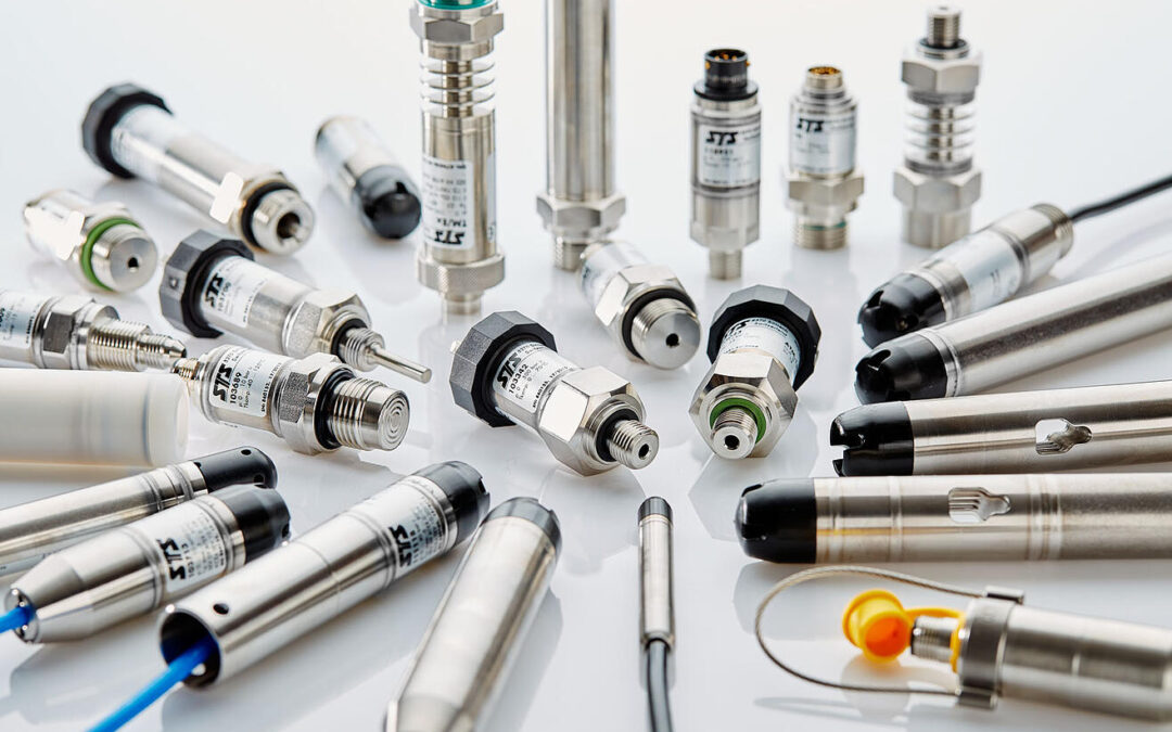
Piezoresistive pressure transmitters excel in their sensitivity, which allows for measuring even the slightest of pressures. The materials employed, however, exhibit a rather high temperature dependence, which then has to be compensated for.

The behavior of a piezoresistive pressure transducer alters in line with temperature. While temperature-related zero offset is self-evident and can be easily recognized and checked by the operator, temperature-related alterations of both sensitivity and linearity are less apparent and thus often overlooked.

Causes of zero offset

The reason for zero offset is a sum of the most varied of effects:

  • differing resistance values at the measuring bridge on the silicon chip
  • varied temperature coefficients of individual resistors in the measuring bridge
  • a non-homogenous silicon membrane, instead coated with a silicon oxide layer (varying expansion coefficients)
  • mechanical tensions when mounting the measuring cells on the carrier (chip, glass, glass feedthrough)
  • oil expansion associated with stiffness of steel membranes (this is why oil volume is minimized to just a few µL in the expansion element)

Depending upon construction of the pressure transducer and the pressure range itself, these individual effects bear relatively great significance. Important in practical terms is not what the thermal zero offset is actually composed of, but instead how well it can be compensated for. Desirable here is as linear a response as possible over as large a temperature range as possible.

Best outcomes with polynomial compensation

Linearity also shifts with temperature. When such temperature effects are to be factored in and compensated for, this is usually only meaningful and possible in the sense of an entirely mathematical modeling of transducer response. This mathematical model precisely describes the full pressure and thermal characteristics of a transducer. To be able to apply this mathematical model, however, a computer or digital compensation methods are required.

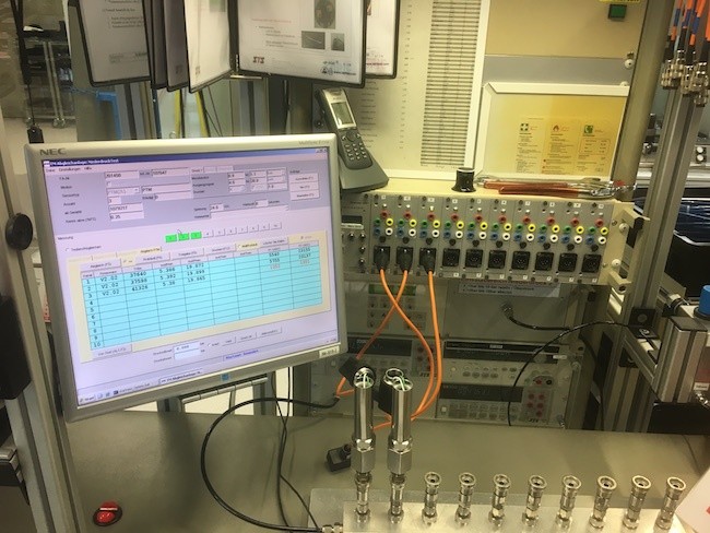
At STS, this is achieved in our OCS products by means of polynomial compensation. The piezoresistive pressure transmitters of the DL.OCS/N/RS485 Datalogger for water monitoring attains for example a precision of 0.03% FS, as well as an accuracy of 0.05% FS over a temperature range from -5…+50 °C by means of polynomial compensation.

The majority of pressure transmitters from STS are optimized as standard for operating temperatures from 0°C to 70°C – an excellent range for achieving precise results in most applications. In some instances, however, it is to advantage when the sensors are delivered pre-optimized for the temperature conditions arising from any particular application. STS is thus specialized in providing application-specific pressure sensors within the shortest of timeframes.

The pressure response of piezoresistive pressure sensors

The pressure response of piezoresistive pressure sensors

Piezoresistive pressure sensors stand out for their high sensitivity. Also in terms of precision and miniaturization, many advantages arise over other measurement instruments. In our knowledge article, we will be explaining the pressure response of piezoresistive pressure sensors.

Users of piezoresistive pressure transducers expect a linear pressure response, in which the output signal is proportional to the applied pressure. For this reason, the curve of the pressure-signal diagram should be a straight line, whose starting point is indicated by the zero position and its sensitivity by the gradient. The true shape of the pressure-signal curve, however, more or less always shows a sharp deviation from the ideal line. This discrepancy is known as the linearity error of the pressure sensor. The gradient of the curve, on the other hand, corresponds to its sensitivity.

We can see from the illustration that a virtually linear part of the curve is utilized when the sensor is used at lower sensitivities (ca. 70% of the nominal chip pressure). Through selection, transmitters can be built of a very low non-linearity (think 0.05 %FS). The prerequisite, however, is that the operating range lies within the linear part of the chip.

The sensitivity of piezoresistive pressure sensors

The sensitivity of a pressure transducer largely depends upon two factors:

  • the resistive value of the diffused semiconductor resistors and their piezoresistive effectiveness level,
  • the thickness of the silicon diaphragm.

The greatest influence upon pressure response lies in the thickness of the silicon diaphragm. This is defined by its mechanical, chemical or even combined processing. These processes cannot be so precisely controlled that all pressure measurement cells exhibit the exact same sensitivity. Classes are thus established within which the pressure sensors can be used for a particular pressure range. And within these classes, sensitivities can vary by around ±20%. This deviation itself can be compensated for in the electronics through the supply current or the amplification factor (calibration).

The linearity of piezoresistive pressure sensors

It should be noted in linearity specifications that %FS (full scale, final value) is mostly applied. In terms of measured value, the error can carry quite significant weight, even when the manufacturer specification lists a very small value, though displayed in %FS.

In pressure measurement cells, the linearity is dependent on several factors:

  • the semiconductor resistors must be sufficiently small and diffused onto the exact right spot on the silicon diaphragm,
  • the silicon diaphragm has to be clean, sharp-edged and in exactly the right place,
  • linearity is varied, whether positive or negative pressure is measured, meaning whether the diaphragm bulges into a concave or a convex form (tensile or compression load),
  • the diameter to thickness ratio of the silicon diaphragm must be within a particular range. Very thin diaphragms will deform with superposed stretching: This balloon-effect, in transducers for lower pressure ranges, leads to a typically S-shaped course of the linearity curve (which cannot be rectified by analog compensation methods).
  • with very thick silicon diaphragms, the intended structure of the diaphragm, rigidly fixed at its edges, is no longer achievable, since, for example, with a 1,000 bar transducer, the diaphragm is half as thick as the chip itself.

The overload and burst pressure of piezoresistive pressure sensors

The typical course of a linearity curve is for the most part quite linear and then more heavily flattened. In the interest of as broad an output signal as possible, the longest possible extent of this curve is utilized. Until around two thirds mark, the course is so linear that error is less than 0.5 %FS. Beyond here, the linearity error becomes rapidly more dominant so that a limit from the accuracy is set. Aside from very low and very high pressure ranges, the nominal pressure range can be exceeded by typically around 50% before the measuring cell fails.

To increase overload protection, the idea of a broad effective signal has to be abandoned: A pressure sensor has to be employed, which would in itself be intended for a higher pressure range. Whilst, for example, a mechanical stop can be deployed in capacitive pressure sensors for its membrane deforming under pressure and a very high overload protection ensured, this is barely possible with the comparatively tiny silicon membranes of piezoresistive pressure cells with their most minimal of deflections.

At STS, the burst pressure is defined as the pressure at which a medium can enter the sensor and hence the metallic diaphragm is destroyed. The transducer, however, is already no longer functional at this point. Using Submersible Sensors the housings, cable connectors and cables are definitive. Burst pressure values of the transducer in the datasheet are thus negligible.

The Long-Term Stability of Pressure Sensors

The Long-Term Stability of Pressure Sensors

Factors such as temperature and mechanical stress can have negative effects on the long-term stability of pressure sensors. However, the effects can be minimized by diligent testing during production.

Manufacturers usually indicate the long-term stability of their pressure sensors in data sheets. The value given in these data sheets is determined under laboratory conditions and it refers to the expected maximum change of zero point and output span in the course of a year. For example, a long-term stability of < 0.1 % FS means that the total error of a pressure sensor may deteriorate by 0.1 percent of the total scale in the course of one year.

Pressure sensors usually take some time to “settle in”. As already mentioned, zero point and sensitivity (output signal) are the main factors to be mentioned here. Users usually notice zero point shifts as they are easy to recognize and to adjust.

How can the long-term stability be optimized?

In order to achieve the best possible long-term stability, which means that only minor shifts occur during the product lifetime, the core element must be right: the sensor chip. A high-quality pressure sensor is the best guarantee for optimal long-term functionality. In the case of piezoresistive pressure sensors, this is the silicon chip on which the Wheatstone bridge is diffused. The foundation of a stable pressure sensor is already laid at the beginning of the production process. A diligent qualification of the silicon chip is hence paramount to the production of pressure sensors with great long-term stability.

The assembly of the sensor is decisive as well. The silicon chip is glued into a casing. Due to the effects of temperature and other influences, the glued-in chip may move and thus also effect the mechanical stress exerted on the silicon chip. Increasingly inaccurate measurement results are the consequence.

Practice has shown that a new sensor takes some time to really stabilize – especially in the first year. The older a sensor, the more stable it is. In order to keep undesirable developments to a minimum and to be able to better assess the sensor, it is aged and subjected to some testing before it leaves production.

How this is done varies from manufacturer to manufacturer. To stabilize new pressure sensors, STS treats them thermally for over a week. The “movement”, which is prone to occur in the sensor in the first year, is thus anticipated to a large extent. Therefore, the thermal treatment is a form of artificial aging.

Image 1: Thermal treatment of piezoresistive pressure measurement cells

The sensor is subjected to further tests in order to characterize it. This includes assessing the behavior of the individual sensor under various temperatures as well as a pressure treatment in which the device is exposed to the intended overpressure over a longer period of time. These measurements serve to characterize each individual sensor. This is necessary in order to make reliable statements about the behavior of the measuring instrument at different ambient temperatures (temperature compensation).

Hence, long-term stability largely depends on the production quality. Of course, regular calibrations and adjustments can help correct any shifts. However, this should not be necessary in most applications: Properly produced sensors will work realiably for a really long time.

How relevant is the long-term stability?

The relevance of long-term stability depends on the application. However, it is certainly of greater importance in the low pressure range. On the one hand, this is due to the fact that external influences have a stronger effect on the signal. Small changes in the mechanical stress of the chip have a greater effect on the precision of the measurement results. Furthermore, pressure sensors produced for low pressure applications are based on a silicon chip whose membrane thickness is often smaller than 10 μm. Therefore, special care is required here during assembly.

Image 2: Detailed view of a bondend and glued silicon chip

Despite all care, an infinite long-term stability and also accuracy is physically impossible. Factors such as pressure hysteresis and temperature hysteresis cannot be completely eliminated. They are, so to speak, the characteristics of a sensor. Users can plan accordingly. For high-accuracy applications, for example, pressure and temperature hysteresis should not exceed 0.02 percent of the total scale.

It should also be mentioned that the laws of physics place certain limits on a sensor’s long-term stability. Wear and tear is to be expected in particularly demanding applications such as applications with fluctuating, high temperatures. Constant high temperatures beyond 150 °C eventually destroy the sensor: the metal layer, which serves to contact the resistors of the Wheatstone bridge, diffuses into the silicon and literally disappears.

Users who use pressure measurements under such extreme conditions or demand the highest level of accuracy should therefore thoroughly discuss options with manufacturers in advance.

Installation of pressure sensors: The medium is decisive to positioning

Installation of pressure sensors: The medium is decisive to positioning

Ideally, pressure transmitters are installed directly within the process to be monitored. If this is not possible, the process medium to be monitored will then decide upon the positioning of those sensors.

There are various reasons why pressure transmitters cannot be mounted directly within the process:

  • there is not enough space for installation within the application
  • the pressure sensors are to be subsequently installed
  • a direct contact between process medium and measuring sensors is undesired (e.g. due to excessive temperatures)

If the pressure sensor cannot be mounted directly in the process, the connection between process and measuring instrument is established via a bypass line (also termed differential pressure line or branch line). This connecting line is filled with gas or liquid, depending on the type of application. As a rule, there will be a shut-off valve both on the bypass line near the process and also near the pressure transmitter. This allows the measuring device (or parts thereof) to be dismantled or modified without interrupting the actual process.

This is particularly helpful when the pressure transmitter is subject to maintenance work, such as calibrations.  The measured medium remains in the bypass line due to the shut-off valve on the measuring instrument.

When laying the bypass lines, a number of important points must be observed. They should be as short as possible, have rounded bends, be free of dirt and their gradients should be as steep as possible (no less than 8%). Additionally, there are also media-specific requirements. For liquids, for example, a complete venting is to be ensured. A bypass line may be used for relative and absolute pressure measurement. For differential pressure measurement, however, there will be two lines. Depending on the process, further installation instructions must also be observed here.

Positioning of pressure transmitters within the process

Depending on the type of process, it is important whether the pressure transmitter is to be mounted above or below that process.  The most important differences between liquid, gas and steam-carrying lines will now be discussed.

Fluids

When measuring fluids in pipelines, the pressure sensor should be installed below the process so that any gas bubbles can then escape back into the process.  Additionally, it must be ensured that the process medium is sufficiently cooled at high temperatures. In this case, the bypass line will also be considered a cooling section.

Gases

For gas measurements on pipelines, the pressure transmitter should, where possible, be mounted above the process. This allows any condensate that may accumulate to flow back into the process without impairing the measurements.

Steam

Steam measurements are somewhat more complex due to the high temperatures and the formation of condensate. Both of these aspects go hand in hand: If the steam cools on its way to the pressure transmitter, a condensate will form. If this should accumulate in the measuring instrument, it can then influence the measured results.

Accordingly, when measuring steam, care must be taken to ensure that the medium temperature is appropriately reduced and that the condensate produced does not enter the pressure transmitter. A height up to which condensate can collect must therefore be defined in advance. This will then be taken into account in the measurement range design. In absolute and relative pressure measurement, the bypass line is curved like an ‘S’ for this purpose.  This leads steeply upwards from the steam-carrying line before dropping downwards again. The condensate will collect in this first pipe bend and can then flow back into the process.

Things become even more complex when measuring differential pressure, since the same conditions should prevail inside both bypass lines. This means that the condensate column is the same on both the high and the low pressure sides. For this reason, condensate vessels, which are still located upstream of the extraction/shut-off valve of the bypass line, are used for steam measurement with differential pressure transmitters. The excess condensate here will then be fed back into the process via these vessels. Additionally, a five-port shut-off valve should be used on the side of the pressure transmitter so that the sensors cannot be permanently impaired by the hot medium, should the bypass line happen to blow out.

Common errors in pressure measurement and how to correct them

Common errors in pressure measurement and how to correct them

Uncertain output signals, zero offsets or even the complete failure of the measuring instrument are symptoms that can quickly strain the nerves of users. The good news is that when the cause is correctly identified, these errors can often be easily corrected.

 In the following, we show you a number of typical errors that users may encounter in practice, but which can usually be avoided with just a little background knowledge. Incidentally, we have already published detailed articles on many of the topics here, which are linked below at the appropriate point.

Error Cause Troubleshooting
No output signal

Line breakage


Check the cable for damage and ensure that it is properly laid.
Wiring error Check the plug-cable assignment and, if necessary, consult the installation and operating instructions.
Wrong polarity
The display indicates too low a pressure Inlet pressure too low due to a blocked port opening
  • Check the port opening for contamination and clean it.
  • If the medium is dirty, a filter should be attached to the process interface.
  • If necessary, use a pressure transmitter with a front-flush membrane.
Pressure transmitter is leaking at the process interface Check the seal, as it is either too loose or defective (with a new seal, check for media compatibility).
The signal is constant but does not exceed a certain value even when the pressure increases The bore opening is blocked
  • Clean the bore opening.
  • Place a filter in front of it.
  • Use a pressure transmitter with a front-flush membrane.
The medium temperature is too low (below -40 °C / -40° Fahrenheit) The measuring cell of a piezoresistive pressure sensor contains a transfer fluid. This can solidify at temperatures below -40 °C. In this case, a pressure transmitter optimized for low temperatures must be selected, with, for example, the AS100 filling fluid (for temperatures down to -55 °C).
The output signal indicates a high value and remains unchanged The permissible measuring range has been exceeded. If the pressure sensor operates in the overload range, it will not yet fail, but does not display accurate measurement results. The output signal has reached saturation point and cannot exceed this any further. A pressure transmitter suited to the measuring range must be selected.
The output signal is too low and does not exceed this low value despite a pressure increase The inlet pressure is too low The port opening is blocked (see above).
Too high a load for mA signals (the electronics connected to the pressure transmitter take too much current) For mA signals, reduce the load according to the data sheet /operating instructions.
Too low a load for V signals Increase the load according to the data sheet/ operating instructions.
Operating voltage too low Operating voltage must be increased in accordance with the operating instructions.
Too wide a measuring range of the pressure transmitter An instrument corresponding to the measuring range must be selected. Rule of thumb is the measuring range should be ca. 75% of device capability.
Zero offset (the zero point signal is too high) The membrane has been deformed by impermissibly high overpressure
  • The pressure transmitter is defective.
  • A suitable measuring range must be selected and, if necessary, a choke used.
The membrane is deformed or ruptured by pressure peaks
Too high tightening torque on installation (measuring cell damaged) This problem is more likely to occur with instruments of a low pressure measuring range. Pay attention to maximum torque during installation at the process (consult mounting instructions).
The output signal shifts greatly under temperature influence There is a blockage to the relative pressure compensation (mostly in devices with low measuring ranges up to 25 bar) The relative pressure compensation should be checked for contamination. It should also be ensured that the installation was carried out correctly.
Strongly fluctuating output signal (flickering) Loose contact A cable break or a loose plug can be the cause.
Strong vibrations or shock pulses in the process The sensor is resonating. Ideally, the permissible shock load should be checked in the data sheet before selecting a pressure transmitter. Shock-resistant devices are characterized by sealed electronics and do without adjustable potentiometers (such as the ATM.1ST). The problem can be solved later by decoupling the measuring device via a flexible pressure line.
The output signal has interference pulses There is too much EMC interference It must be ensured that the cables are shielded.  EMC phenomena can be mostly eliminated with careful installation.
Differing potentials between measuring instrument and process Check the ground connection of the pressure transmitter.
The output signal fails after some time in operation The electronic components fail due to a too high operating temperature The process medium can be sufficiently cooled via a temperature decoupler, such as upstream cooling fins or a cooling section.A siphon is the best solution for steam applications.

Some of the errors listed here are due to incorrectly selected pressure transmitters. To avoid errors, you should know in advance as precisely as possible the requirements for the measuring instrument with regards pressure measurement range and installation (a short guide to the correct transmitter selection can be found here). A detailed consultation beforehand with the manufacturer can help spare your nerves. But we’d also be glad to assist you further

Position can influence the accuracy of pressure transmitters

Position can influence the accuracy of pressure transmitters

The accuracy of a pressure measurement can definitely be influenced by the position of the pressure transmitter. Particular attention to this should be paid in the low-pressure range.

When it comes to position dependence, inaccuracies can occur if the position of the pressure transmitter differs in practice from that used during the calibration process at the manufacturer. At STS, the norm is for pressure transmitters to be calibrated in a vertical position pointing downwards (see accompanying image above). If users now mount one of these calibrated pressure sensors in the opposite position, i.e. pointing vertically upwards, then inaccuracies may occur during the pressure measurement.

The reason for this is simple. In the latter position, the actual weight of the pressure transmitter will influence its precision. The membrane, filling body and transmission fluid act upon the actual sensor chip due to the gravitational force of the earth. This behavior is common to all piezoresistive pressure sensors, but it is only of importance in the low-pressure range.

Installation of pressure transmitters: Caution in the lower pressure ranges

The lower the pressure to be measured, the higher in this case the measurement error will be. With a 100 mbar sensor, the measurement error amounts to one percent. The higher the measuring range, the lower the effect becomes. Starting from a pressure of 1 bar, this error becomes practically negligible.

This measurement inaccuracy can be easily detected by users, especially when a relative pressure sensor is used. If users are working in the low-pressure range and it is not possible to mount the measuring instrument in the position in which it was factory calibrated, it should then be recalibrated in its actual position. Alternatively, users can also compensate for the measurement error themselves numerically on the control unit.

This additional effort can, of course, be easily avoided through competent application advice. Although STS pressure transmitters are calibrated vertically downwards as standard, it is easily possible to carry out the calibration in a different position. Our advice is to communicate the mounting position of your pressure transmitter with us in advance and you will then receive a measuring instrument perfectly matched to your application.

We will be only too happy to advise you!

Subscribe To Our Newsletter

Join our mailing list to receive the latest news and updates from our team.

You have Successfully Subscribed!