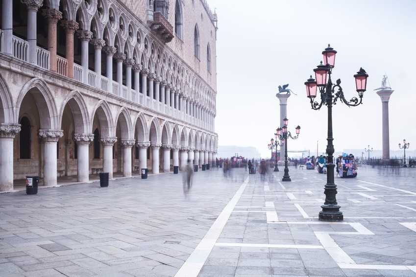
Level loggers monitoring water levels in Venice
The Piazza San Marco will never flood: Level data loggers from STS are in use to continuously measure groundwater levels at the Piazza San Marco. These are particularly robust and are also suited for application in various scenarios.
In 2003, the company of S.P.G. began to install several groundwater dataloggers at the Piazza San Marco in Venice. These were designed for the specific demands and possess, above all, the attribute of withstanding several days submerged in saline waters, since on rising tides, Piazza San Marco is regularly flooded. The site operates in conjunction with efforts initiated by the water regulatory authority for protecting the lagoons and the city of Venice from flooding.
The appointed consortium of Venezia Nuova earmarked the wharfage opposite the Piazza San Marco with innovative technical features. The challenge consisted of monitoring the flow of groundwater, which was by degrees shifting from the site area to the buildings located behind. At the client’s request, level data loggers from STS were installed to continuously measure the fluctuations in groundwater levels.
The groundwater datalogger permits a simultaneous measurement of level, temperature and conductivity in ranges of 0…50 cmWS to 0…250 mWC, -5 to 50 °C and 0.020…20 mS/cm. When required, the end user can at any time retrofit a data transmission unit. The logger features a simple, user-friendly operation, an extended measurement memory for up to 1.5 million readings and a probe diameter of only 24 mm or 10 mm.
The plug-in units also allow for the possibility of cable extension. New software functions can also be updated without their requiring inconvenient return through the end user. The standard lithium batteries can be changed on site in no time. Data can be transferred in ASCII or XML format and further processed using standard software such as Excel. Variable data-saving intervals dependent on pressure or time allow for versatile measurements.
Through the use of various materials including stainless steel, titanium, PUR, PE or Teflon cable, a high medium tolerance is attained for the most varied of applications, such as landfills, contaminated sites, pump trials, high-water alarms and discharge/overflow logging in rain overflow basins.
Original publication: Konstruktion magazine