Vibrations: The pressure sensor is also affected

Vibrations: The pressure sensor is also affected

In virtually all applications where compressors, turbines and motors come into play, vibrations are to be found, which also affect measurement sensors. Without appropriate precautions, this can impair the functionality of the pressure transducers employed.

The effects of vibration on pressure sensors can be serious: On the one hand, the measurement signal can be disturbed by superimposition. If this vibration is transmitted to the output signal, end users will not receive useful measurement results. This effect can be observed without any delay and a continuous load here can also lead to material fatigue. Welding seams can break apart and threaded connections become loose. Whether through distorted measurement results or broken mechanical connections, vibrations can render pressure sensors inoperable. Fortunately, these undesirable effects can also be largely minimized.

Preventing damage to the pressure measurement system by vibrations

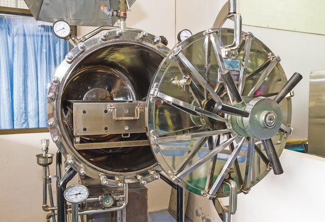
Prevention is the best measure. This requires that users are aware of the vibrations occurring in the respective application. The first step is to determine the vibration frequency of the application. Vibrations do not cause damage per se. In manufacturers’ data sheets, the frequency range in which no interference occurs is often listed under “Tests”. The DIN EN 60068-2-6 standard is applied here, where the test specimen is subjected to a defined frequency range over a predetermined test duration. The aim here is to specify the characteristic frequencies of the test specimen. The actual test procedure is shown in Figure 1.

Figure 1: Qualification of a prototype: Pressure sensor is screwed into an aluminum block that is loaded mechanically (vibration, acceleration)

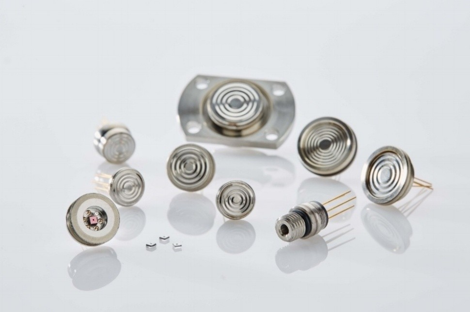
If strong vibrations arise that exceed the specifications of the pressure sensor, two approaches can be initially considered. The first is concerned with spatial dimension: How big is the pressure transducer and where is it installed? It holds true that the heavier and larger a pressure transducer is, the greater the effect of the vibrations and the lower the resistance. It may thus be advantageous in strongly vibrating applications to use a smaller pressure transmitter, such as the ATM.mini, which suffers little effect from vibrations due to its small mass.

Besides the dimensions of the pressure transducer, its actual position in the application is also decisive. If it sits along the vibration axis, then it will receive less vibration. When it is mounted across the vibration axis, however, it must be able to withstand the full extent of those vibrations.

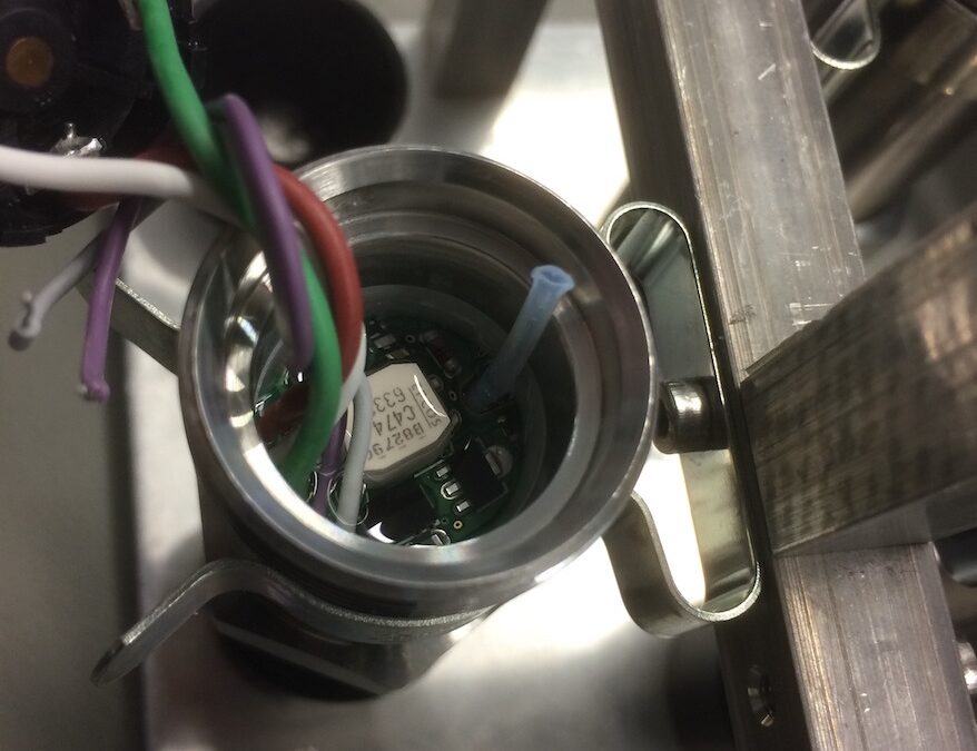
In addition, the pressure transducer itself can be equipped to even better tolerate vibrations. For this purpose, the pressure transmitter is encased in a soft sealing compound, which dampens the vibrations and thus adequately protects the mechanical components. In Figure 2 this sealing compound is seen as transparently glossy.

Figure 2: Pressure sensor with sealing compound 

In summary, it can be said that strong vibrations could damage the measurement sensor. By selecting a pressure transmitter suitable for the application (frequency range, dimensions) as well as optimal mounting (along the vibration axis), the effects of any vibrations can be minimized. Further protection is provided by encasing the sensor in a dampening sealer compound (see Figure 2). 

High Accuracy Pressure Measurement at High Temperatures

High Accuracy Pressure Measurement at High Temperatures

In some applications, pressure transmitters have to work reliably when exposed to very high temperatures. Autoclaves used to sterilize equipment and supplies in the chemical and food industries are certainly one of these demanding applications.

An autoclave is a pressure chamber used in a wide range of industries for a variety of applications. They are characterized by high temperatures and pressure different from ambient air pressure. Medical autoclaves, for example, are used to sterilize equipment by destroying bacteria, viruses and fungi at 134 °C. Air trapped in the pressure chamber is removed and replaced by hot steam. The most common method for achieving this is called downward displacement: steam enters the chamber and fills the upper areas by pushing the cooler air to the bottom. There, it is evacuated through a drain that is equipped with a temperature sensor. This process stops once all air has been evacuated and the temperature inside the autoclave is 134 °C.

Very accurate measuring at high temperatures

Pressure transmitters are used in autoclaves for monitoring and validation. Since standard pressure sensors are usually calibrated at room temperature, they cannot deliver the best accuracy under the hot and wet conditions encountered in autoclaves. However, STS has recently been approached by a client in the pharmaceutical industry that requires a total error of 0,1 percent at 134 °C measuring -1 to 5 bar.

Piezoresistive pressure sensors are rather sensitive to temperature. However, temperature errors can be compensated so that the devices can be optimized for the temperatures encountered in individual applications. For example, if you use a standard pressure transmitter that achieves 0,1 percent accuracy at room temperature, the device would not be able to deliver the same degree of accuracy when used in an autoclave with temperatures of up to 134 °C.

Users who know that they require a pressure sensor that achieves a high degree of accuracy at high temperatures hence need a device that is calibrated accordingly. Calibrating a pressure sensor for certain temperature ranges is one thing. However, the client who inquired about the autoclave application with very high accuracy demands had another challenge for us that was even trickier to realize than a properly calibrated sensor: not only the sensor element was to be in the autoclave at 134 °C, but the complete transmitter including all electronics had to go in there, too. Unfortunately, we cannot go into specifics as to how we were able to assemble a digital transmitter that both delivers the desired accuracy of less than 0,1 percent total error at 134 °C but whose other components can handle the hot and moist conditions as well.

In short: Piezoresistive pressure sensors are sensitive to temperature changes. However, with the right know-how, they can be optimized for the requirements of individual applications. Moreover, not only the sensor element can be calibrated accordingly, the whole transmitter can be assembled in a way that even hot and wet conditions can be managed.

Electronic pressure measurement: Comparison of common measuring principles

Electronic pressure measurement: Comparison of common measuring principles

Electronic pressure transmitters are used in a variety of applications, from machine technology to the manufacturing sector right through to the foodstuffs and pharmaceuticals industries. The recording of the physical size of pressure can take place via different measuring principles. We introduce the common technologies here.

In electronic pressure measurement, a distinction is usually made between thin-film sensors, thick-film sensors and piezoresistive pressure sensors. It is common to all three measurement principles that the physical quantity of pressure is converted into a measurable electrical signal. Equally fundamental to all three principles is a Wheatstone bridge: a measurement device for the detection of electrical resistances, which itself consists of four interconnected resistors.

Piezoresistive pressure sensors: High-precision and cost-effective

Piezoresistive pressure sensors are based on semiconductor strain gauges made of silicon. Four resistors connected to a Wheatstone bridge are diffused onto a silicon chip. Under pressure, this silicon chip will deform and this deformation then alters the conductivity of the diffused resistors. The pressure can then ultimately be read from this shift in resistance.

Because the piezoresistive sensor element is very sensitive, it must be shielded from the influence of the measuring medium. The sensor is therefore located inside a diaphragm seal, with pressure being transmitted via a liquid surrounding the sensor element. The usual choice here is silicone oil. In hygienic applications such as in the foodstuffs or pharmaceuticals industries, however, other transfer fluids are also used. A dry measuring cell from which no liquid will escape in the event of damage is not possible.

The advantages:

  • very high sensitivity, pressures in the mbar range measurable
  • high measuring range possible, from mbar to 2,000 bar
  • very high overload safety
  • excellent accuracy of up to 0.05 percent of span
  • small sensor design
  • very good hysteresis behavior and good repeatability
  • basic technology comparatively inexpensive
  • static and dynamic pressures

The disadvantages:

Thin-film sensors: Long-term stability but expensive

In contrast to piezoresistive pressure sensors, thin-film sensors are based on a metallic main body. Upon this, the four resistors connected to a Wheatstone bridge are deposited by a so-called sputtering process. The pressure is thus detected here also by a change in resistance caused by deformation. Besides the strain gauges, temperature compensation resistors can also be inserted. A transfer liquid, as in the case of piezoresistive pressure sensors, is not necessary.

The advantages:

  • very small size
  • pressures up to 8,000 bar measurable
  • outstanding long-term stability
  • no temperature compensation required
  • high accuracy
  • high burst pressure
  • static and dynamic pressures

The disadvantages:

  • lower sensitivity than piezoresistive sensors, so low pressures are less measurable
  • basic technology comparatively expensive

Thick-film sensors: Particularly corrosion-resistant

Ceramics (alumina ceramics) serve as the basic material for thick-film sensors. These pressure sensors are monolithic, meaning that the sensor body consists of only one material, which ensures an excellent long-term stability. Furthermore, ceramics are particularly corrosion-resistant against aggressive media. With this type of sensor, the Wheatstone bridge is printed onto the main body by means of thick-film technology and then baked on at high temperature.

The advantages:

  • very good corrosion resistance
  • no temperature compensation required
  • good long-term stability
  • no diaphragm seal needed

The disadvantages:

  • not suitable for measuring dynamic pressures
  • limited upper pressure range (about 400 bar)
Correctly interpreting accuracy values for pressure sensors

Correctly interpreting accuracy values for pressure sensors

In the search for a suitable pressure transmitter, various factors will play a role. Whilst some applications require a particularly broad pressure range or an extended thermal stability, to others accuracy is decisive. The term “accuracy”, however, is defined by no standards. We provide you with an overview of the various values.

Although ‘accuracy’ is not a defined norm, it can nevertheless be verified from values relevant to accuracy, since these are defined across all standards. How these accuracy-relevant values are specified in the datasheets of various manufacturers, however, remains entirely up to them. For users, this complicates the comparison between different manufacturers. It thus comes down to how the accuracy is presented in the datasheets and interpreting this data correctly. A 0.5% error, after all, can be equally as precise as 0.1% – it’s only a question of the method adopted for determining that accuracy.

Accuracy values for pressure transmitters: An overview

The most widely applied accuracy value is non-linearity. This depicts the greatest possible deviation of the characteristic curve from a given reference line. To determine the latter, three methods are available: End Point adjustment, Best Fit Straight Line (BFSL) and Best Fit Through Zero. All of these methods lead to differing results.

The easiest method to understand is End Point adjustment. In this case, the reference line passes through the initial and end point of the characteristic curve. BSFL adjustment, on the other hand, is the method that results in the smallest error values. Here the reference line is positioned so that the maximum positive and negative deviations are equal in degree.

The Best Fit Through Zero method, in terms of results, is situated between the other two methods. Which of these methods manufacturers apply must usually be queried directly, since this information is often not noted in the datasheets. At STS, the characteristic curve according to Best Fit Through Zero adjustment is usually adopted.

The three methods in comparison:

Measurement error is the easiest value for users to understand regarding accuracy of a sensor, since it can be read directly from the characteristic curve and also contains the relevant error factors at room temperature (non-linearity, hysteresis, non-repeatability etc.). Measurement error describes the biggest deviation between the actual characteristic curve and the ideal straight line. Since measurement error returns a larger value than non-linearity, it is not often specified by manufacturers in datasheets.

Another accuracy value also applied is typical accuracy. Since individual measuring devices are not identical to one another, manufacturers state a maximum value, which will not be exceeded. The underlying “typical accuracy” will therefore not be achieved by all devices. It can be assumed, however, that the distribution of these devices corresponds to 1 sigma of the Gaussian distribution (meaning around two thirds). This also implies that one batch of the sensors is more precise than stated and another batch is less precise (although a particular maximum value will not be exceeded).

As paradoxical as it may sound, accuracy values can actually vary in accuracy. In practice, this means that a pressure sensor with 0.5% error in maximal non-linearity according to End Point adjustment is exactly as accurate as a sensor with 0.1% error of typical non-linearity according to BSFL adjustment.

Temperature error

The accuracy values of non-linearity, typical accuracy and measurement error refer to the behavior of the pressure sensor at a reference temperature, which is usually 25°C. Of course, there are also applications where very low or very high temperatures can occur. Because thermal conditions influence the precision of the sensor, the temperature error must additionally be included. More about the thermal characteristics of piezoresistive pressure sensors can be found here.

Accuracy over time: Long-term stability

The entries for accuracy in the product datasheets provide information about the instrument at the end of its production process. From this moment on, the accuracy of the device can alter. This is completely normal. The alterations over the course of the sensor’s lifetime are usually specified as long-term stability.  Here also, the data refers to laboratory or reference conditions. This means that, even in extensive tests under laboratory conditions, the stated long-term stability cannot be quantified precisely for the true operating conditions. A number of factors need to be considered: Thermal conditions, vibrations or the actual pressures to be endured influence accuracy over the product’s lifetime.

This is why we recommend testing pressure sensors once a year for compliance to their specifications. It is essential to check variations in the device in terms of accuracy. To this end, it is normally sufficient to check the zero point for changes while in an unpressurized state. Should this be greater than the manufacturer’s specifications, the unit is likely to be defective.

The accuracy of a pressure sensor can be influenced by a variety of factors. It is therefore wholly advised to consult the manufacturers beforehand: Under which conditions is the pressure transmitter to be used? What possible sources of error could occur? How can the instrument be best integrated into the application? How was the accuracy specified in the datasheet calculated? In this way, you can ultimately ensure that you as a user receive the pressure transmitter that optimally meets your requirements in terms of accuracy.

Characteristic curve, hysteresis, measurement error: Terminology in pressure measurement technology

Characteristic curve, hysteresis, measurement error: Terminology in pressure measurement technology

The first data sources for users of pressure measurement technology are often the data sheets supplied by the manufacturers. Of particular interest here is usually the accuracy data. In this context, a large number of terms appear whose comprehension is of great importance in assessment of that particular measurement instrument.

On the topic of accuracy, it can be fundamentally stated that the term itself is not subject to any defined standard. This, however, is not the case for the terminology arising in association with accuracy specifications, including characteristic curve, hysteresis, non-linearity, non-repeatability, and measurement error. In the following, we will briefly explain these terms.

Characteristic curve

The characteristic curve indicates the dependence of the output signal (measured value) upon the input signal (pressure). In the ideal scenario, the characteristic curve will be a straight line.

Non-linearity

The greatest deviation (positive or negative) of the characteristic curve from a reference line is described as non-linearity. The reference line itself can be determined by three different methods: End Point adjustment, Best Fit Straight Line(BFSL) and Best Fit Through Zero. Each of these methods arrives at different results, with Limit Point adjustment being the most commonly used method in Europe. The reference line here runs through the start and end point of the characteristic curve.

Measurement error

The measurement error, or measurement deviation, describes the shift of the displayed value from the “correct” value. This “correct” value is an ideal one, which in practice can only be attained with a highly accurate measuring device under reference conditions, such as a primary standard as would be used in calibration. The measurement error is expressed as either an absolute or a relative error. Absolute error is listed in the same units as the measured value, whereas relative error refers to the correct value and remains unit-free.

Zero point and span errors

In sensor production, there are deviations from the reference device (standard). Measurement deviations at the measuring range start and end points are referred to as zero point and span errors. The latter relates to the difference between the two values. The zero point error is the difference between the ideal zero point of the target characteristic line and the true output value of the actual characteristic curve.

Zero point error can be easily read off by the user in an unpressurized state. In order to eliminate it, the user must then enter this as an offset into the evaluation unit. Elimination of the span error is somewhat more difficult, since the pressure at the end of the measuring range must be approached precisely.

Hysteresis

The displayed value measured depends not only on the input variable (here, pressure), but also on the values measured previously from the input variable.

If the characteristic curve of the measuring device is recorded with continuously increasing pressure and then compared with the characteristic curve at continuously decreasing pressure, it is noticeable that the output signals, despite identical pressures, are not themselves exactly identical. The maximum deviation between these two characteristic curves is termed hysteresis and is expressed as a percentage of full scale (% FS).

Non-repeatability

Even when measured under identical conditions, electronic pressure transmitters are subject to stochastic influences, because of which the output signal is not identical at the same pressure values over successive measurements. The biggest deviation over three successive measurements taken from the same direction of approach is thus expressed as non-repeatability. A reliable pressure measuring device is recognized by users from its lowest possible non-repeatability.

Similar to hysteresis, non-repeatability cannot be compensated for.

Temperature error

Temperature changes directly affect the characteristics of a pressure sensor. The electrical resistance of semiconductors, as used in piezoresistive pressure transmitters, decreases with increasing temperature, for example. Manufacturers therefore optimize their products by way of a balanced thermal characteristic. Temperature-related errors are either compensated for directly on the sensor or are performed electronically. Some devices also have a temperature sensor that directly compensates for these temperature-related errors. All the same, errors such as this can only be minimized but not completely eliminated. This residual temperature error is indicated by some manufacturers as a temperature coefficient.

Overload pressure – Overpressure

The specified error limits are exceeded into the overload range. The pressure transmitter, however, suffers no lasting damage.

Burst pressure

The burst pressure indicates the pressure at which deformation of the pressure transducer occurs, where it becomes mechanically damaged.

Long-term stability

External influences affect the measuring instrument. For this reason, the characteristic curve does not remain constant over years of use. The long-term stability (also long-term drift) is determined by manufacturers under laboratory conditions and listed in data sheets as a percentage of full scale per annum.

The actual operating conditions of the device can however differ significantly from the test conditions. Test procedures between manufacturers can also vary widely, which makes comparability of the data even more difficult. In general, it is recommended that the pressure transducer be calibrated at regular intervals and, if necessary, adjusted.

Accuracy: Non-conformity of a curve

As mentioned at the outset, “accuracy“ is not a fixed value. Another term occasionally used for accuracy is non-conformity of a curve. This describes the maximum total error according to IEC 770 and comprises the linearity deviation and hysteresis, as well as non-repeatability. It is therefore the deviation from the ideal characteristic line at the end value of the measurement range and is expressed as a percentage.

Download the free STS infographic on total error here:

Subscribe To Our Newsletter

Join our mailing list to receive the latest news and updates from our team.

You have Successfully Subscribed!