Testing of proportional pressure regulators in hydraulic systems

Testing of proportional pressure regulators in hydraulic systems

When testing proportional pressure regulators as part of the development of complex hydraulic systems, high impulse capability and precision are required from the pressure measurement sensors employed.

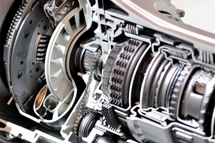
In the development of new hydraulic systems, in automotive engineering, for example, a large number of components need to mesh together perfectly. In addition to experience gained and the models employed, test loops on the test bed play an important role here. Do the components arriving from suppliers meet the specifications? Are optimum results already achieved here in the overall system?

In oil-hydraulic systems such as vehicle clutches, the pressure valves used are of great importance. As mechanical components, they need to be thoroughly qualified in order to minimize negative effects such as overshoots or adverse flow effects. A valve that is not working optimally has a negative effect across the entire system. What pressure peaks can be expected and how do they affect the system? How must the valve be designed so that coupling processes are as smooth and vibration-free as possible? Precise pressure measurement plays a key role in clarifying these questions. Numerous tests are necessary before a harmonious overall system can be created and these negative effects can be largely eliminated. However, since these tests are not limited to the pressure valve alone, but instead carried out across the entire system, the demands upon the sensors used are correspondingly high.

Pressure measurement in hydraulic systems: Top performance is required

As an experienced partner for pressure measurement tasks in the Test & Measurement sector, STS has already supported a large number of projects related to the testing of proportional pressure regulators in hydraulic systems. Accordingly, we are very familiar with the high demands to be expected in the pressure measurement of pressure valves in oil-hydraulic systems.

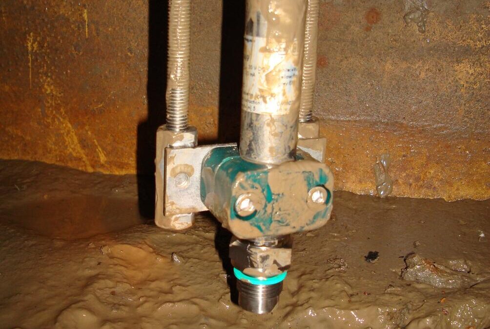
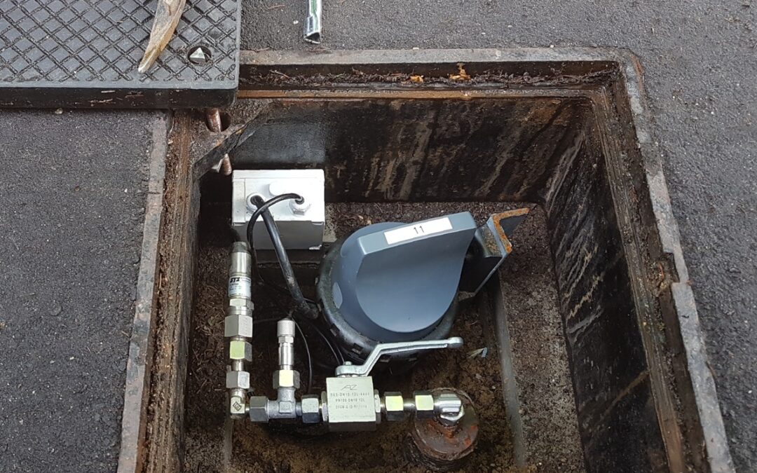
Due to the increasingly complex tasks involved in the qualification of hydraulic systems, space has now become a decisive criterion. These systems are nowadays equipped with a large number of sensors and so the smaller the better, therefore. In order to meet these requirements with regard to miniaturization of sensor technology, STS introduced the ATM.mini, a precision pressure transmitter with external dimensions of only 17.5 x 49 millimeters, which is now being used on numerous test beds. Flexibility with regard to installation is also required, since the sensors don’t just have to fit in terms of space. Also in terms of the process connections, there are always other specifications that have to be fulfilled. Finally, we can say from experience that the selection and installation of the sensor technology often follows the development of an application on the test bed and must be able to comply with the facts established there. For this reason, STS follows a modular design principle so that all products can be adapted to individual specifications. This, of course, also applies to the ATM.mini.

Apart from physical size, the “intrinsic values” are also decisive. If we return now to the example of hydraulic systems in automotive engineering, a very good impulse capability is essential for continuous measurements during the tests. It must be possible to record pressures dynamically within mere milliseconds of one another. In addition, this must proceed highly precisely over a relatively broad temperature range from -30 to 140°C. The non-linearity can often be a maximum of only 0.1 percent of the full scale measurement value (you can read more about precision here). This ultimately implies also that the pressure transmitter is largely insensitive to vibrations. Another important factor during the testing of components in a hydraulic system is that pressure peaks can always occur, the extent of which cannot be precisely determined in advance. For applications of this type, a pressure transmitter whose overload capability is many times the measuring range will thus be required.

The ATM.mini manufactured by us meets all of these requirements. Your advantages in summary:

  • pressure range from 0-1 bar to 0-100 bar
  • outstanding accuracy of 0.1% FS
  • compact design of outer dimension 17.5 x 49 millimeters
  • highest precision over the entire temperature range
  • compensated temperature range from -40 to 125 °C
  • no media incompatibility due to welded pressure port
  • individually adaptable solutions through modular construction
Applications of pressure measurement technology in the marine industry

Applications of pressure measurement technology in the marine industry

Sensor technology plays an essential role in the maritime sector and most particularly in shipbuilding. The dependable and accurate measurement of pressure, temperature and other variables within various tanks is an important measure in preventing the escape of aggressive fluids, controlling water circulation systems in ship operations and also in guaranteeing a smooth transportation of cargo across the high seas. 

The sensor technology employed here has to meet numerous stringent requirements. These include, above all, that the materials utilized are robust enough for use over the longer term. The electronics must also be capable of withstanding the harsh conditions of the open seas and therefore remain highly durable.

Monitoring of dry and liquid cargoes

The main component of freight consists of wares to be shipped, with both dry and liquid cargoes being transported by sea. Dry cargo is the term we use when bulk goods such as grain and animal feed, as well as piece goods usually held in containers, are being transported. Liquid cargoes, however, require particularly careful and reliable monitoring, since highly sensitive substances, including gasoline, oil and gas oil, are usually being transported here. The products employed must be particularly robust and reliable in order to prevent the escape of aggressive liquid substances and thus prevent accidents of the gravest ecological consequences. This means that sensory systems must also meet the very highest of demands.

Freshwater and wastewater tanks

On cargo ships, fresh or drinking water is either carried in special potable water tanks or obtained from seawater through a purification treatment. The collection, treatment and disposal of ship wastewater in internal storage systems must also be monitored using an appropriate technology. Since this wastewater is often contaminated with harmful substances, such as oils or cleaning agents, its processing also remains subject to certain additional requirements. Both freshwater and wastewater tank systems are checked and monitored using built-in sensors. In this way, the systems can be monitored most efficiently, which in turn guarantees an optimum water supply across the high seas.

Ballast tanks

Ballast tanks are an important part of shipping. Without loading these tanks, large cargo ships can sometimes be too light, meaning that their propellers will not sit deep enough in the water. To ensure a sufficient draught, the ballast tanks are filled up with seawater and can even be used to even out the weight distribution across a loaded ship. Since these tanks are being filled with saltwater, both the materials of the tanks and those of the sensors used must be robust and corrosion-resistant. Special attention is also paid to high reliability and durability, since the sensors are virtually inaccessible underway during on-board operation and must therefore function perfectly without any manual maintenance or inspection.

Image 1: Level measurement installation options

Special sensory requirements

Over the last few years, the shipbuilding industry has seen a steady stream of decisive innovations to which the production of sensors employed must respond accordingly. Whereas 15 years ago, for example, the durability of stainless steel was still a major concern, today we recognize that it corrodes when it comes into contact with saltwater at temperatures above 21 degrees Celsius. Nowadays, titanium is employed instead. STS recognized this problem early on and was one of the first companies to use titanium as a permanent component of its sensing technology. This extremely stable and robust material is now used as standard for a wide range of pressure transmitters and immersion probes, since it can withstand even the most adverse of conditions.

The technological requirements are constantly changing as the industry itself grows and evolves. What was considered standard a short time ago may already be inadequate by today. STS is therefore constantly striving to further develop the sensing technology it offers, thus guaranteeing reliability and accuracy, even in the face of increasing industrial demands. This flexibility and quality does pay off, however, with return rates negligibly low and problems more likely to arise from human error than through faulty technology.

Collaboration with AE Sensors

For over 27 years now, STS has been working together with the Dutch family-run company AE Sensors. Together, we supply major customers in the shipbuilding industry with their sensing technology. With competent consulting and the use of flexible solutions, our customers have been able to record enormous growth in just a short period of time. By now, state-of-the-art vessels are being built at shipyards all over the world, in which submersible probes, pressure transmitters and other tailor-made solutions from STS are being used. Above all, our ATM/N and ATM.1ST/N sensors made of titanium and fitted with Teflon cables are being deployed as standard.

Thanks to their modular mounting system, installation of our sensors can be variably adapted to the prevailing requirements. Various forms of measurement, such as positive or absolute pressure, may also be implemented. The high flexibility of STS and our partner AE Sensors, combined with the flawless quality of our sensing technology, has proven itself over many years of cooperation with our satisfied customers.

Pressure unlocks Compressed Natural Gas’ potential

Pressure unlocks Compressed Natural Gas’ potential

Thanks to its very high energy density, compressed natural gas (CNG) is well suited for use as an automotive fuel. CNG has an octane number of approximately 120 and combustion heat of 9,000 to 11,000 kcal/ kg or 38 to 47 MJ/ kg.

In addition, the combustion of CNG produces significantly less CO2 emissions than does the combustion of gasoline, for example. And because CNG is a particularly cost-effective fuel in many markets, manufacturers are showing a growing interest in developing vehicles that are capable of running on this alternative fuel source.

The primary challenge in optimizing an Internal Combustion Engine to run on CNG is regulating the injection pressure in the fuel rail.

Image 1: Example of a two fuel system for gasoline and CNG
Image Source: Bosch Mobility Solutions

CNG is stored at approximately 200 Bar, and is commonly injected at between two to nine Bar, depending on the engine requirements – low pressure for fuel efficient driving in the lower speed ranges, and higher pressures when greater power and torque are required.

The effectiveness of combustion within an engine’s cylinder is strongly influenced by the temperature and pressure of the CNG: An increase in pressure at constant volume will result in higher mass density of the gas, thus increasing its heating value.

However, even though the initial temperature and injection pressure can be varied, if not accurately calibrated during development, compressed natural gas vehicles can suffer from power loss and poor drivability.

Injecting CNG under pressure

Typically, CNG is fed from a high-pressure tank via a pressure regulator to the fuel rail. For efficient fuel combustion, the amount of natural gas injected must always be matched to the mass of air required by the engine. To achieve this the electronic engine management typically employs an air-flow meter to determine the exact amount of air required and subsequently the quantity of CNG to be injected.

With central point injection (CPI), the CNG is fed from a natural-gas distributor (NGD) into the intake manifold. A medium-pressure sensor measures the pressure and temperature in the NGD, allowing the natural-gas injectors to deliver the precise amount of fuel required.

Alternatively, the injection can also be implemented without the NGD, by aligning each injector with a corresponding cylinder. With this multi-point injection (MPI), the gas is injected under pressure at each cylinder’s intake manifold ‘runner,’ upstream of the intake valve.

Because changes in pressure have a significant influence on the engine’s performance when running on CNG fuel, engine torque and exhaust emissions (CO, CO2, NOx and hydrocarbons) all have to be recorded during engine testing.

Optimizing rail pressure for all driving conditions

To optimize the CNG system it’s important that during the design and testing phases the pressure within the rail is accurately measured at various throttle openings and cross referenced to engine torque and the corresponding exhaust gas emissions. Consequently high quality pressure sensors are demanded by most development engineers.

It’s important that these sensors deliver accurate readings across a wide range of pressures, while retaining their integrity at elevated temperatures.

Although an increase in CNG pressure reduces CO2, HC and NOx, CO in the exhaust gas increases, making it vital to accurately record the effects of modulating the CNG injection pressure.

During testing a pressure regulator is used to control injection pressure which is measured by an accurately calibrated pressure sensor located in the rail, while an analog flow meter, typically with a capacity of 2.5 m3/ h,is used to measure and control the inlet air flow rate. A chassis dynamometer is used to record engine torque.

For the duration of the test, gas temperature and flow rate are kept constant at 22°C and 0.1 SCFH, respectively. A high power blower is used to maintain engine temperature during the test, and emission test equipment is attached to the exhaust outlet to record CO, CO2, hydrocarbons and NOx content in the exhaust gases.

The process is quite complex and requires rail pressure, torque and emissions to be measured at hundreds of throttle opening points in order to create an effective map of the engine’s requirements for the engine ECU.

Measuring, recording and inputting all this data into the relevant tables is a time consuming task, therefore development engineers often turn to modeling tools to fast-track development. These tools commonly provide an environment for simulation and model-based design for dynamic and embedded systems, thereby reducing the number of hardware versions required to design the system.

The simulation model is coded with the information gained from the real-time testing and then built into an executable using C compiler to run on a real time operating system.

Once the baseline data is captured it’s possible to generate an infinite number of real-time simulations to be applied to any facet of the design cycle – from initial concept, to controller design, test and validation using hardware-in-loop (HIL) testing.

A well-developed test program using laboratory grade pressure sensors and test equipment unleashes performance and drivability from CNG fueled vehicles that is comparable to fossil fueled equivalents, while delivering cost and emissions benefits.

Mud Logging Requires High-Performing, Rugged Pressure Transmitters

Mud Logging Requires High-Performing, Rugged Pressure Transmitters

The term mud logging refers to the analytical methods that are performed on drilling mud during drilling operations. Powerful and, above all, rugged pressure transmitters are paramount to the process.

The words “mud” and “logging” already provide a good, albeit incomplete, description of the process involved: mud loggers (also surface-logging specialists) are tasked by drilling companies to create detailed records of a borehole. Mud loggers analyze the information brought to the surface during the drilling process, which is why many companies also use the term surface logging services (SLS). The drilling mud is the most important component of mud logging as it carries the information from the depth of the borehole to the surface, where the cuttings (i.e. pieces of formation rock) contained in the circulating drilling medium are examined.

These findings provide a depth-dependent protocol to determine the depth position of hydrocarbons, identify borehole lithology, and monitor natural gas that may enter the drilling mud. Further objectives of mud logging are estimating the pore pressure and porosity as well as permeability of the drilled formation, collecting, monitoring and evaluating hydrocarbons, and assessing the producibility of hydrocarbon-bearing formations as well as keeping a record of drilling parameters. This data is important to ensure safe as well as economically optimized drilling operations.

Mud logging takes place in real time in mobile laboratories that are set up at the drilling site. The real-time data is directly used for drilling control. Mud logging services are usually carried out by specialists contracted by the drilling company. STS is providing pressure transmitters to some of these providers of surface logging services.

Pressure sensors used in drilling processes: durability is key

In order to monitor the drilling process, mud loggers mount various sensors on the drilling apparatus. The detection of even minor losses of drill pipe pressure requires a very high degree of accuracy. Moreover, an immediate response is necessary as well to prevent fishing times, lost-in-holes as well as the risks and costs associated with abnormalities.

Drilling sites are rugged environments and as such can be very demanding on the sensor equipment. The two most important factors in this regard are the mud itself and the vibrations that are to be expected in drilling operations.

Image 1: ATEX certified pressure transmitter for Mud Logging applications

To deal with these harsh conditions, STS provides companies offering surface logging services with the ATM/ECO/EX with customized housing. The ATEX-certified pressure transmitter is optimized for high pressure ranges. The vibrations occurring during drilling processes largely affect the area between the tube and the process connection. STS solved the issue by double welding the connection. Moreover, the stainless steel tube is thicker than is usually the case (26,5 mm). Other than the high pressure ranges and the vibrations that have to be accounted for, the mud presents another challenge by potentially clogging the pressure channel. To prevent clogging, we made the channel a bit wider (10 mm). Normally, a wider pressure channel can put the pressure diaphragm at risk. However, since mud loggers largely work with static pressures, this is not an issue.

Gas distribution grid monitoring by continuous pressure measurement

Gas distribution grid monitoring by continuous pressure measurement

The autonomous process loggers from the firm AIRVALVE operate with pressure sensors from STS in monitoring critical points of the gas grid owned by SWK Netze GmbH. The principle applied here affords planning reliability at a comparatively low outlay in its implementation.

SWK Netze GmbH performs extensive measurements on its gas distribution grid for calibration of its pipeline program. To this end, continuous pressure measurements are to be made at fifteen critical points as part of its project “Grid Monitoring of the Gas Distribution Network.” Besides expectations of the most precise of measured values, it was also crucial upon realization of this project that the measurement instruments performed both reliably over a longer time span and simultaneously had sufficient signal strength to regularly transmit measurements even when mounted below ground. To reduce underground and pipe installation work to an absolute minimum, pressures were instead to be measured at already existing ventilation fittings. For this purpose, the measurement equipment was to be installed in size 3 street caps.

To fulfill this task, the selection went to process loggers of the type LS-42 produced by AIRVALVE. During extensive testing, it previously emerged that the products of this process logger series were the only to avail of an integrated high-performance antenna, which could provide for an undisturbed signal transmission even in underground shaft workings.

Long-term stability and user-friendliness are key factors

In addition, this measurement instrument, thanks to its high-performance, interchangeable battery, functions free from electrical and telephone connections over a duration of 10 years and more. This easily mounted process logger, which is also remotely configurable, ensures a secure transmission of the measured readings due to freely selectable SIM cards or multi-network with a private VPN tunnel (see Fig. 1 about design of the process logger). It is therefore perfectly suited to remote or poorly accessible facilities, which have to be monitored over a longer timeframe without arduous maintenance requirements.

Figure 1: Datalogger construction (Source: AIRVALVE)

These requirements in terms of durability and operational performance were, of course, also placed upon the sensors used for pressure measurement. AIRVALVE opted here for the ATM.ECO/N pressure transmitters from STS.  These 100 mbar sensors are provided with power from the interchangeable battery of the process logger, have a resilient stainless steel housing and deliver precise results to an accuracy of ≤ ± 0.70 % over a temperature range from -5 to 50°C. In terms of long-term stability, the ATM.ECO/N registers < 0.5 %.


Assembly of the measuring system on the gas distribution grid

The entire measuring system for monitoring the gas distribution grid is housed in street caps (see Fig. 2). By using already existing ventilation fittings, the work necessary could be performed without major outlay. To implement pressure measurements, the ventilation riser plug was replaced with a reducer fitting (1). Using a stainless steel ball valve, the measurement connection can be shut-off (2). Calibration of the pressure sensor is facilitated by a Minimess coupling (3). The pressure sensor (4) is connected via a pressure-equalizing junction box (5) to the AIRVALVE process logger (6). This is then fixed to a ground anchor (7) by a click fastener.

Figure 2: Overview of the measuring system (Source: AIRVALVE)

Measurements are performed every 5 minutes. This measuring interval is fundamentally selectable between one and sixty minutes. The measured values are transmitted several times daily to the control center. Transmission of the readings can take place over VPN-secured multi-network cards or basic agreement SIM cards. Communications are possible using internet control centers or also with SCADA systems. In this example application, SWK Netze GmbH opted for the “Web-LS” internet control center to manage the obtained data through highly secure servers.

Subscribe To Our Newsletter

Join our mailing list to receive the latest news and updates from our team.

You have Successfully Subscribed!