Electronic pressure measurement: Comparison of common measuring principles

Electronic pressure measurement: Comparison of common measuring principles

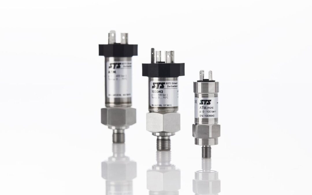
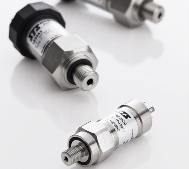
Electronic pressure transmitters are used in a variety of applications, from machine technology to the manufacturing sector right through to the foodstuffs and pharmaceuticals industries. The recording of the physical size of pressure can take place via different measuring principles. We introduce the common technologies here.

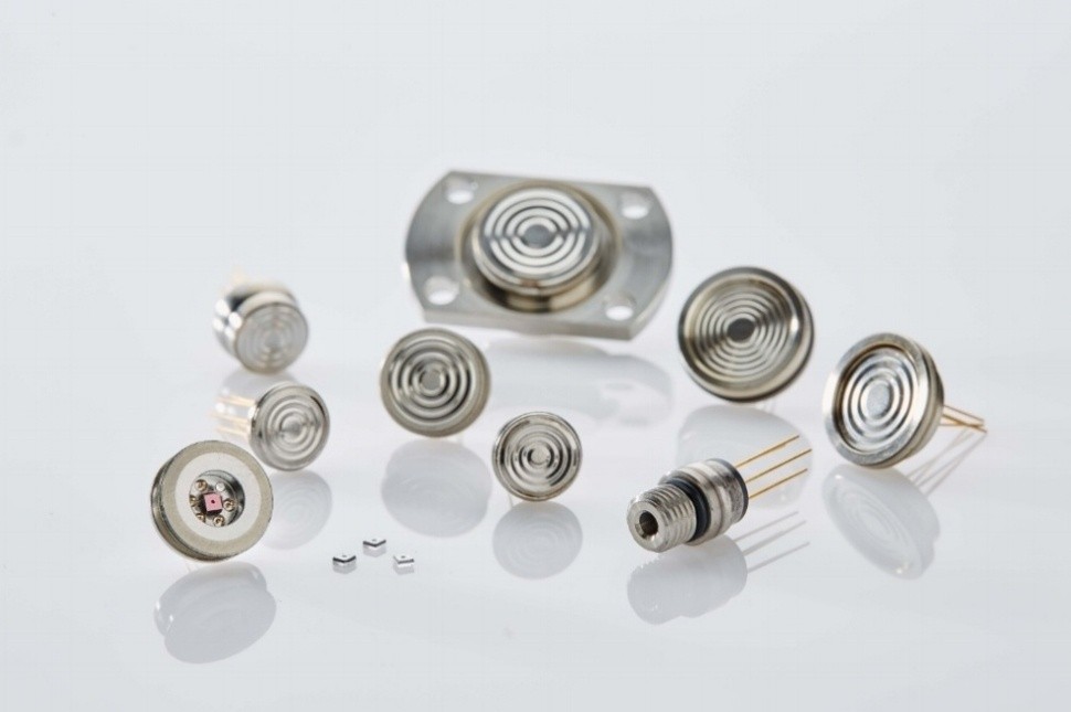
In electronic pressure measurement, a distinction is usually made between thin-film sensors, thick-film sensors and piezoresistive pressure sensors. It is common to all three measurement principles that the physical quantity of pressure is converted into a measurable electrical signal. Equally fundamental to all three principles is a Wheatstone bridge: a measurement device for the detection of electrical resistances, which itself consists of four interconnected resistors.

Piezoresistive pressure sensors: High-precision and cost-effective

Piezoresistive pressure sensors are based on semiconductor strain gauges made of silicon. Four resistors connected to a Wheatstone bridge are diffused onto a silicon chip. Under pressure, this silicon chip will deform and this deformation then alters the conductivity of the diffused resistors. The pressure can then ultimately be read from this shift in resistance.

Because the piezoresistive sensor element is very sensitive, it must be shielded from the influence of the measuring medium. The sensor is therefore located inside a diaphragm seal, with pressure being transmitted via a liquid surrounding the sensor element. The usual choice here is silicone oil. In hygienic applications such as in the foodstuffs or pharmaceuticals industries, however, other transfer fluids are also used. A dry measuring cell from which no liquid will escape in the event of damage is not possible.

The advantages:

  • very high sensitivity, pressures in the mbar range measurable
  • high measuring range possible, from mbar to 2,000 bar
  • very high overload safety
  • excellent accuracy of up to 0.05 percent of span
  • small sensor design
  • very good hysteresis behavior and good repeatability
  • basic technology comparatively inexpensive
  • static and dynamic pressures

The disadvantages:

Thin-film sensors: Long-term stability but expensive

In contrast to piezoresistive pressure sensors, thin-film sensors are based on a metallic main body. Upon this, the four resistors connected to a Wheatstone bridge are deposited by a so-called sputtering process. The pressure is thus detected here also by a change in resistance caused by deformation. Besides the strain gauges, temperature compensation resistors can also be inserted. A transfer liquid, as in the case of piezoresistive pressure sensors, is not necessary.

The advantages:

  • very small size
  • pressures up to 8,000 bar measurable
  • outstanding long-term stability
  • no temperature compensation required
  • high accuracy
  • high burst pressure
  • static and dynamic pressures

The disadvantages:

  • lower sensitivity than piezoresistive sensors, so low pressures are less measurable
  • basic technology comparatively expensive

Thick-film sensors: Particularly corrosion-resistant

Ceramics (alumina ceramics) serve as the basic material for thick-film sensors. These pressure sensors are monolithic, meaning that the sensor body consists of only one material, which ensures an excellent long-term stability. Furthermore, ceramics are particularly corrosion-resistant against aggressive media. With this type of sensor, the Wheatstone bridge is printed onto the main body by means of thick-film technology and then baked on at high temperature.

The advantages:

  • very good corrosion resistance
  • no temperature compensation required
  • good long-term stability
  • no diaphragm seal needed

The disadvantages:

  • not suitable for measuring dynamic pressures
  • limited upper pressure range (about 400 bar)
Ensuring EMC When Installing Pressure Transmitters

Ensuring EMC When Installing Pressure Transmitters

The term electromagnetic compatibility (EMC) refers to the operation of electrical devices in an electromagnetic environment. Neither should the electromagnetic environment cause interferences in the device nor should the device cause interferences in said environment. EMC phenomena can also have a negative impact on the operation of pressure transmitters. Knowledge of these phenomena is valuable during the installation process in order to preclude electromagnetic interferences (EMI) in advance.

EMC phenomena should always be taken into account when choosing installation locations where electrical devices of all types are present, especially those with high power consumption. These are, just to name a few examples, frequency converters, voltage transformers, pumps and generators.

In general, EMC regulations are specified in various standards (for example EN 61000). Whether a pressure sensor complies with these standards is usually indicated in the product data sheets of the manufacturer, often under the heading “tests”.

EMC phenomena associated with pressure transmitters

Ideally, typical problems associated with EMC are already excluded during installation planning. After installation, electromagnetic interferences can be identified by unexpected measurement results (plausibility check) or an interrupted signal transmission.

In our experience, disturbances are often caused by one of the three EMC phenomena capacitive coupling, inductive coupling or galvanic coupling, which are briefly described below.

Capacitive coupling

Capacitive coupling occurs when electrical conductors with different electrical potentials and a common reference conductor are installed close to each other (millimeters to centimeters). It is therefore a distance-dependent phenomenon in which an electrical charge transfer occurs from one electrical conductor to the other.

Capacitive coupling can falsify the measurement results of analogue pressure transmitters when the interference occurs at the moment of measurement. The pressure transmitter’s electrical output signal is falsified and hence the user receives an incorrect pressure value.

Inductive coupling

If electrical conductors are installed close to each other, their magnetic fields are superimposed. The magnetic field strength of a conductor changes when a current change occurs. A typical example would be switching on a pump. The rule is: the larger the current, the stronger the magnetic field. The sudden change in the magnetic field strength manifests itself in an interference voltage in the adjacent electrical conductors. This phenomenon can also occur together with capacitive coupling. The resulting measurement errors are similar to those already described in the capacitive coupling section above.

Galvanic coupling

If several circuits are conductively connected or use the same conductor, galvanic coupling may occur. In practice, this can be observed when high and low power devices share the same power supply. Current changes in the device with high power consumption can cause a voltage drop in the common conductor and are coupled as a noise in the circuit of the device with low power consumption. This can lead to measurement errors in analog pressure transmitters. The phenomenon rarely occurs with digital measuring devices.

EMC of Analog and Digital Pressure Transmitters

EMC of Analog and Digital Pressure Transmitters

Regarding electromagnetic compatibility (EMC), the demands of the individual application are decisive: Although we live in the age of digitization, this does not mean that “digital” is always the best solution. This also applies to pressure transmitters.

Analog pressure transmitters have been known for over 150 years and have been created as a result of the Industrial Revolution. They have survived almost unchanged for a long time. Modern production processes have produced more stable, more accurate and smaller analog pressure transmitters. The emergence of digital pressure measurement technology in the second half of the last century could not displace their analog relatives. There are good reasons for this: digital pressure transmitters are not suitable for every application. 

Digital vs. analog pressure sensors: comparison

The signal of analog devices is transmitted as an analog current or voltage signal. The most commonly used is the 4-20 mA standard signal, followed by 0-10 V, and less often 0.5 – 4.5 Vrat. In piezoresistive pressure sensors, pressure is measured by the deformation of a membrane. The deformation of the membrane leads to a change in resistance to the diffused resistors connected to each other to form a Wheatstone measuring bridge. This resistance change is converted as an electrical signal. The compensation of zero or span error is also done via analog circuitry.

Digital pressure sensors use digital interfaces such as RS-485 with Modbus to transmit the measured values. Therefore, they can also be referred to as fieldbus transmitters. In contrast to analog pressure sensors, the electrical signal of the resistance change is directly digitized. The compensation of typical errors such as temperature error is realized through a microprocessor. 

When are analog pressure sensors the best option?

This short comparison shows that digital pressure transmitters offer a multitude of advantages. These are also practical: the signal from an analog pressure sensor has to be digitized before it can be processed. If the measured value has to be directly visualized on a display, for example, a digital signal is an advantage. Moreover, digital pressure transmitters are the only option when measurements have to be made available remotely. Digital gauges are also important when pressure is used as a control variable in an automated process control system.

Both digital and analog pressure transmitters can deliver high-precision results. Nevertheless, digital pressure transmitters have a slight advantage, particularly in applications with very high accuracy requirements since all compensations are purely digital. However, if dynamic processes need to be measured, analog pressure sensors are often the better option.

Despite this apparent superiority of digital pressure sensors, their analog counterparts are still useful. On the one hand, the distinction between analog and digital is also a matter of costs. If you do not need the advantages of a digital measuring instrument, you should not pay extra for it. However, this economic consideration is not the only reason why analog devices are more suitable than digital ones in some cases: The 4-20 mA standard output signal used by most analog pressure transmitters is largely immune to inductive coupling.

Inductively coupled noise: things to consider

Analog pressure transmitters are often the safest choice when used in an environment with high voltage noise caused by magnetic fields. Still, this is not a reason to completely forgo digital pressure transmitters in such environments. Precautions can prevent or sufficiently restrict interference from inductive coupling when installing the pressure transmitter.

Take a pump application as a simple example in this regard. When switching on the pump, there is a momentary high current flow that creates a correspondingly large magnetic field. If the connecting line of the pressure transmitter is installed parallel to the pump, it is within the influence of this magnetic field. The resulting voltage causes interference in the pressure transmitter. The disturbances vary depending on the pressure transmitter: With analog devices there is a “noise” in the measured values. With digital pressure transmitters, the signal transmission can completely collapse.

In this example, it would therefore be advisable to carefully consider the position of the connecting line during installation. However, this might not be an option in some applications. In this case, the cable screen should be properly grounded to divert the interference signals into the earth (read more about grounding here).

The Long-Term Stability of Pressure Sensors

The Long-Term Stability of Pressure Sensors

Factors such as temperature and mechanical stress can have negative effects on the long-term stability of pressure sensors. However, the effects can be minimized by diligent testing during production.

Manufacturers usually indicate the long-term stability of their pressure sensors in data sheets. The value given in these data sheets is determined under laboratory conditions and it refers to the expected maximum change of zero point and output span in the course of a year. For example, a long-term stability of < 0.1 % FS means that the total error of a pressure sensor may deteriorate by 0.1 percent of the total scale in the course of one year.

Pressure sensors usually take some time to “settle in”. As already mentioned, zero point and sensitivity (output signal) are the main factors to be mentioned here. Users usually notice zero point shifts as they are easy to recognize and to adjust.

How can the long-term stability be optimized?

In order to achieve the best possible long-term stability, which means that only minor shifts occur during the product lifetime, the core element must be right: the sensor chip. A high-quality pressure sensor is the best guarantee for optimal long-term functionality. In the case of piezoresistive pressure sensors, this is the silicon chip on which the Wheatstone bridge is diffused. The foundation of a stable pressure sensor is already laid at the beginning of the production process. A diligent qualification of the silicon chip is hence paramount to the production of pressure sensors with great long-term stability.

The assembly of the sensor is decisive as well. The silicon chip is glued into a casing. Due to the effects of temperature and other influences, the glued-in chip may move and thus also effect the mechanical stress exerted on the silicon chip. Increasingly inaccurate measurement results are the consequence.

Practice has shown that a new sensor takes some time to really stabilize – especially in the first year. The older a sensor, the more stable it is. In order to keep undesirable developments to a minimum and to be able to better assess the sensor, it is aged and subjected to some testing before it leaves production.

How this is done varies from manufacturer to manufacturer. To stabilize new pressure sensors, STS treats them thermally for over a week. The “movement”, which is prone to occur in the sensor in the first year, is thus anticipated to a large extent. Therefore, the thermal treatment is a form of artificial aging.

Image 1: Thermal treatment of piezoresistive pressure measurement cells

The sensor is subjected to further tests in order to characterize it. This includes assessing the behavior of the individual sensor under various temperatures as well as a pressure treatment in which the device is exposed to the intended overpressure over a longer period of time. These measurements serve to characterize each individual sensor. This is necessary in order to make reliable statements about the behavior of the measuring instrument at different ambient temperatures (temperature compensation).

Hence, long-term stability largely depends on the production quality. Of course, regular calibrations and adjustments can help correct any shifts. However, this should not be necessary in most applications: Properly produced sensors will work realiably for a really long time.

How relevant is the long-term stability?

The relevance of long-term stability depends on the application. However, it is certainly of greater importance in the low pressure range. On the one hand, this is due to the fact that external influences have a stronger effect on the signal. Small changes in the mechanical stress of the chip have a greater effect on the precision of the measurement results. Furthermore, pressure sensors produced for low pressure applications are based on a silicon chip whose membrane thickness is often smaller than 10 μm. Therefore, special care is required here during assembly.

Image 2: Detailed view of a bondend and glued silicon chip

Despite all care, an infinite long-term stability and also accuracy is physically impossible. Factors such as pressure hysteresis and temperature hysteresis cannot be completely eliminated. They are, so to speak, the characteristics of a sensor. Users can plan accordingly. For high-accuracy applications, for example, pressure and temperature hysteresis should not exceed 0.02 percent of the total scale.

It should also be mentioned that the laws of physics place certain limits on a sensor’s long-term stability. Wear and tear is to be expected in particularly demanding applications such as applications with fluctuating, high temperatures. Constant high temperatures beyond 150 °C eventually destroy the sensor: the metal layer, which serves to contact the resistors of the Wheatstone bridge, diffuses into the silicon and literally disappears.

Users who use pressure measurements under such extreme conditions or demand the highest level of accuracy should therefore thoroughly discuss options with manufacturers in advance.

Subscribe To Our Newsletter

Join our mailing list to receive the latest news and updates from our team.

You have Successfully Subscribed!