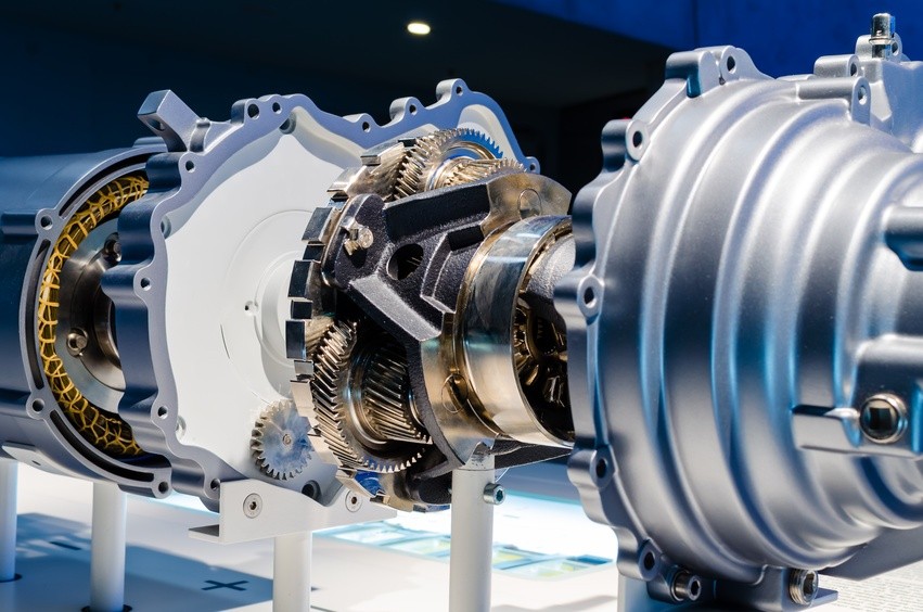
The turbocharger succumbs to the pressures of energy conservation
For many years turbochargers were only found on expensive sports cars and diesel powered engines, but emissions regulations changed the way the world viewed forced induction. Although at the core was still the quest to improve performance, now manufacturers were looking at restoring performance and driveability to downsized fuel-sippingengines. So in the 21stCentury, almost everything from the little 999 cm3 Ford Ecoboost to the latest Ferrari’s all gained shiny new turbo technology.
But almost as soon as the tech came into its own it seems set to become redundant, upstaged by the new eCharger. Already Audi’s fitted this to the series production SQ7 and will be rolling out the technology to future production vehicles as 48 Volt electrification gains traction.
The key advantage to the electrically driven supercharger is that, as with turbochargers, there are no parasitic losses; but unlike most turbo’s there’s no turbo lag either and no need for a wastegate. The powerful electric motor can spool up the impeller to 70,000 rpm in less than a second, which eliminates turbo lag.
This naturally improves driveability and reduces consumption and emissions by between 7 and 20 percent when the device is used on a vehicle equipped with regenerative braking, which captures the car’s kinetic energy and turns it into electricity.
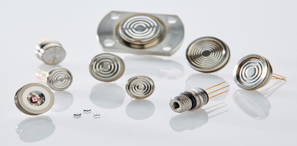
Pressure is key to unlocking the eCharger’s performance
Electronically controlled, the eCharger can be mapped to optimize engine performance while maximizing the energy recovered from the exhaust gas, but in order to achieve this Utopia, engineers need to create a map of the boost the engine requires by measuring manifold pressures at various engine loads and speeds. This can only be done with the aid of top quality pressure sensors.
As with any super/ turbo-charger, it’s important that the unit is matched to the engine’s requirements: Failing to do this, will either starve the engine or result in unnecessary electrical power consumption.
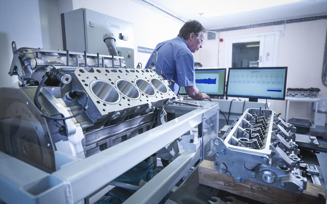
Being a maturing technology, not much research and testing data is available to engineers wishing to explore the boundaries of eCharge superchargers. Although fluid dynamics and electrical engineering can provide good foundations from which to build, it’s still vital that theories are validated under real-world test conditions.
In order to qualify the performance, once the baseline eCharger has been selected, the vehicle is equipped with extremely accurate pressure sensors that are readily calibrated and provide precise readings over a wide range of manifold boost pressures and temperatures. These sensors must also be resistant to vibration and chemical degradation.
Both on the engine dynamometer as well as road testing, throttle position/ engine speed/ Manifold air Pressure and temperatures are continuously recorded to ascertain the interrelationship of these key inputs.
From this information, engineers are able to verify that the correct eCharger configuration has been selected whilst at the same time ensuring that the closed loop engine management controls are able to correctly respond to the key variables.
The result of getting this right delivers a vehicle, such as the SQ7, which has stunning performance, drive ability and fuel consumption whilst still meeting future global emissions regulations.