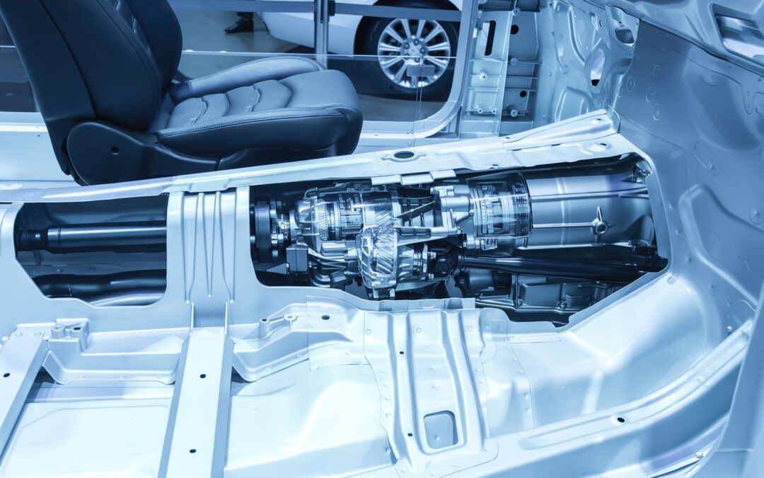
Automatic transmissions thrive under pressure

Automatic transmissions thrive under pressure

Although several attempts were made to design a transmission that selected gears automatically, it wasn’t until 1939 that the engineers at General Motors came up with a satisfactory solution; the device was called HydraMatic, and it was the first fully automatic passenger car transmission to reach production, with about 25,000 Oldsmobiles equipped with them being sold.

Nearly twenty-five years later, in 1963, Earl A. Thompson who had been in charge of the group of GM engineers which developed the HydraMatic, received the Sperry Award, in recognition of “a distinguished engineering contribution which, through application, proved in actual service, has advanced the art of transportation whether by land, sea, or air.”

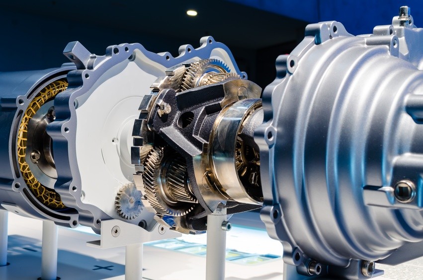
Over the next 75 years, the Automatic Transmission (A/T) gained another five (Or even six) speeds, become electronically controlled and shrunk in size. But after all these years the A/T still relies on hydraulic line pressure to function.

Hydraulic line pressure controls the behavior of the automatic transmission 

The valve body is the control center of the automatic transmission.  It contains a maze of channels and passages that direct hydraulic fluid to the numerous valves which then activate the appropriate clutch pack or band servo to shift to the right gear for each driving condition smoothly.

Each of the many valves in the valve body has a particular purpose and is named for that function. For example, the 2-3 shift valve activates the 2nd gear to 3rd gear up-shift, or the 3-2 shift timing valve which determines when a downshift should occur.

The most important valve is the manual valve which is directly connected to the gear shift lever and covers and opens various passages depending on what position the gear shift is placed in.  When in Drive, for instance, the manual valve directs fluid to the clutch pack(s) that activates 1st gear. It’s also setup to monitor vehicle speed and throttle position so that it can determine the optimal time and force (Dependent on engine load and speed) for the 1 – 2 shift.

On computer controlled transmissions electrical solenoids are fitted to the valve body which direct fluid to the appropriate clutch packs or bands under computer control to more precisely control shift points.

The pressure generated by the oil pump is channeled to mainline, governor, and throttle pressure valves to control and lubricate the transmission. Some of these have been replaced or work together with electronic controls.

  • Governor pressure increases with vehicle speed. Older transmissions had mechanical governors that consisted of springs, centrifugal weights, and a spool valve to control this pressure. Governor pressure determines the transmission upshift whilst throttle pressure decides the downshift. Today’s transmissions use solenoids for shift timing.
  • Throttle pressure indicates engine load. Some transmissions use a vacuum modulator or throttle linkage to control the throttle valve. Late model vehicles use electric solenoids to achieve the same results.

Transmissions change gears by moving shift valves. Governor pressure works on one end of the valve and throttle pressure aided by a spring operates on the other. When a vehicle first accelerates from a stop, throttle pressure is higher than governor pressure, so the car stays in first gear. As vehicle speed increases, the governor pressure (affected by vehicle speed) increases until it overcomes throttle pressure and causes an upshift.

A downshift occurs when throttle pressure overcomes governor pressure. This is because of the increased engine load. These two pressures control shift valve movement. Shift valves control the reactionary devices (clutches and bands) that drive and clamp members of the planetary gear set.

To achieve a smooth gear-change without excessive “slip” is no mean feat: The pressure, locking one set of bands and releasing another, has to, not only be correctly timed but has to be applied in a manner that gives a firm shift without shock. This is all controlled through the hydraulic line pressure.

During development of the A/T port line pressures are measured in real time and compared to design norms to confirm that design parameters are being met. At the same time, shift times and quality are measured and subjectively evaluated to ensure driveability and performance goals are achieved. This can only be done through highly accurate, quality pressure transmitters such as those produced by STS.

These measurements recorded during development are critical, not only for establishing quality shifts but also for developing unique specifications pertaining to the particular transmission. These are used for fault diagnosis at repair shops.

Keeping pace with the times

With emissions regulations playing a significant role in the development of modern vehicles, manufacturers continue to rethink the design, with an eye on improving efficiencies without detracting from performance.

In one such development undertaken by Korean manufacturer KIA, 143 new technologies were patented during the design of the compact 8AT. This new transmission enables smooth acceleration from a standstill, as well as greater fuel efficiency, improved NVH characteristics, and more decisive acceleration at high speeds than an automatic transmission with fewer gears.

To improve the eight-speed automatic transmission’s fuel economy, KIA engineers significantly reduced the size of the oil pump (the primary source of power loss in an automatic transmission) and simplified the structure of the valve body. Boasting the smallest oil pump of any production transmission in its class, the 8AT is able to use hydraulic oil more efficiently, distributing it evenly throughout the unit at all times.

KIA’s development teams also incorporated a direct control valve body to allow solenoid control of the clutch directly, rather than via several control valves. This enabled KIA to reduce the number of control valves from 20 to 12, resulting in quicker gear shifts, a more direct mechanical link to the engine and improved packaging.

The challenge in this revolutionary approach was to ensure that the smaller pump was capable of supplying sufficient volumes of hydraulic fluid at pressures up to about 20 bar to the various components required for the operation of the A/T.

During developmental tests the mainline pressures were measured under idle and wide open throttle conditions, with the unit at operating temperature, to ensure that the smaller pump was up to the task. Once again, because of the critical nature of the results obtained from these tests only high-quality laboratory certified pressure transmitters were used.
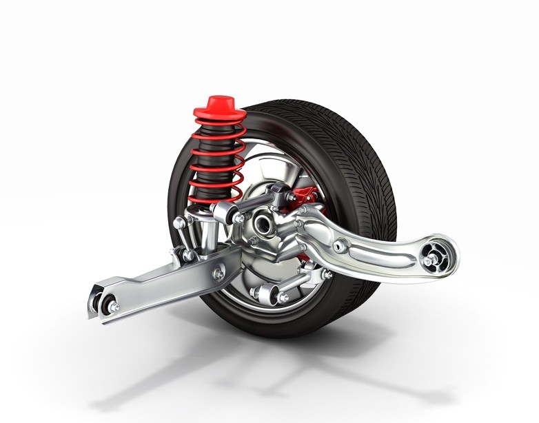
Smoother than a Roller, better than a race car: Active suspension comes of age

Smoother than a Roller, better than a race car: Active suspension comes of age

Colin Chapman is regarded as an automotive visionary in racing circles: His two noteworthy achievements in the technological stratosphere known as Formula One racing, were the development of “Ground effects” and “Active suspension.” Both of which were subsequently banned from F1, but adopted and developed for road cars.

Even the early road going iterations of the Chapman penned active suspension showed significant gains over their semi-active counterparts.

However the early Lotus system, which used hydraulic rams to move the wheels, cost thousands of dollars, added 150 Kilograms, and required about four Kilowatt to drive the system’s 140 Bar hydraulic pump. Furthermore, the system couldn’t respond quickly enough to smooth out the small sharp bumps that plague most roads.

Active suspension relies on accurate pressure measurement during development

In trying to smooth out the bumps in developing hydraulically interconnected suspension (HIS) it was obvious that the optimization of the system lay with control and response of the actuators that regulated the wheel movement. Not only did these need to generate the forces involved in supporting the car, traversing rough terrain and negotiating turns in the road, but they also had to react in a fraction of a second: And key to this was the operating pressure of the system and how this was controlled.

To achieve the performance and response targets engineers had to overcome several challenges, including:

  • Hydraulic fluid used to drive the system never operates at a constant temperature and viscosity, thereby impacting on the delivery pressures.
  • Precise control of the appropriate pressure relied on extremely accurate real time line-pressure measurement, with temperature compensation.

The pressure sensors used during development had to be of laboratory quality and have a very quick response to changes in pressure. Even today there are only a handful of manufacturers that are capable of manufacturing these high quality components to the standards required by the industry.

Although the hydro-mechanical HIS active suspension improved exponentially, the costs involved in achieving the response time were staggering, limiting the systems to a few top-end sports and luxury cars.

Finally smart control ushers in intelligent suspension

It wasn’t long before manufacturers began turning to electronic processors and control units to exercise precise control over the hydraulics controlling the actuators. This has finally empowered the engineers to precisely control the pressure routed to individual actuators thereby improving response time and performance over a wide range of operating conditions.

That’s exactly what Mercedes Benz’s Magic Body Control (MBC) does. A camera situated at the top of the windshield scans the road ahead, analyzing its flaws and blemishes, and feeds that data directly to the Active Body Control (ABC) system’s control unit. The camera scans the area 4.5 to 13.5 Meters in front of the car, and can detect and measure imperfections as small as 10mm. In doing so, the system knows exactly what the tires will encounter, fractions of a second before the event. This allows the active suspension time to prepare the suspension for the appropriate ride-control.

Using the input from the cameras the MBC can even “retract” a wheel prior to impact with a pothole, thereby preventing the wheel from dropping all the way into the hole. This obviously does a great deal to lessen the impact and improve the ride quality.

Even though active suspension has been integrated into the larger ADAS (Advanced Driver Assist Systems) architecture, many systems still rely on the precise control of the hydraulic line pressure to achieve the desired ride and handling. And at the root of this is a high quality pressure sensor that provided the development engineers with accurate data, upon which they could base the algorithms that control the modern active suspension system.

It’s time to rethink engine cooling

It’s time to rethink engine cooling

All internal combustion engines experience significant energy “loss” due to the inefficient conversion of chemical energy into heat and subsequently, kinetic energy. Even a modern F1 engine is relatively wasteful when it comes to converting the power available from the fuel/air mixture into power at the rear wheels. This is measured in terms of ‘thermal efficiency,’ and is typically in the region of 30%: that’s to say, if a typical F1 engine produces slightly under 650 KW on the dyno, something like another 1500 KW does no work in propelling the car.

So where does it go? A small percentage is turned into the distinctive sound of an F1 car. The vast majority, though, must be dissipated as heat from a number of areas: for example, the oil dispels around 120 KW and the water system 160 KW. The inefficiencies of the gearbox will mean it has to dissipate around 15 KW, while the hydraulics represent a further 3 KW.

In these high-performance engines, the coolant systems are commonly pressurized up to 3.75 bar and have a boiling point around 120°C.

In the modern passenger car, coolant system pressures are characteristically in the order of between 0.9 to 1.1 bar, raising the boiling point by about 22°C  resulting in an engine coolant operating temperature of about 100°C.

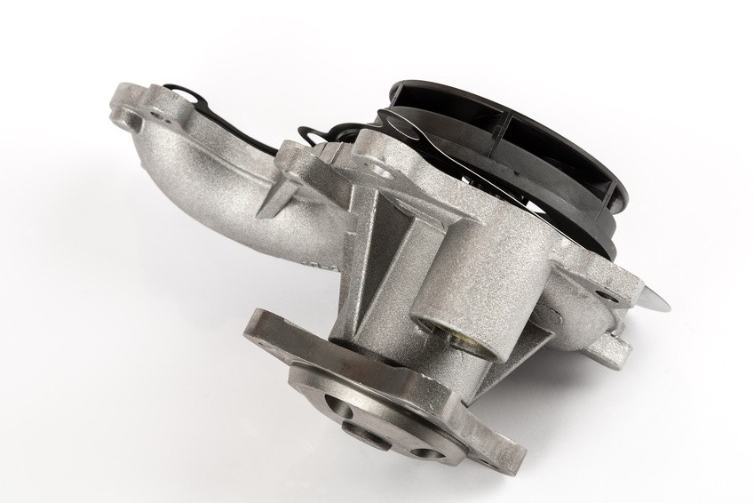
At the same time, a typical water pump can move a maximum of about 28,000 liters of coolant per hour, or recirculate the coolant in the engine over 20 times per minute, whilst drawing off up to 2 KW in parasitic losses.

These figures are well known and have been used as a rule of thumb by automotive engineers for over 100 years: But downsizing to meet ever tightening emissions requirements, and the proliferation of hybrid electric vehicles are changing the rules.

Going electric saves power, but beware the pressure

Manufacturers are studying, in depth, all parasitic losses in an endeavor to increase the efficiency of current and future powertrains. This includes a relook at the coolant system, and in particular the mechanical water pump.

Whilst the decoupling of the water pump from the engine achieves significant savings, it basically requires a requalification of the entire cooling system’s performance; including the operating pressures under varying temperatures, and engine speeds.

With the delivery of the electric motor no longer directly proportional to the engine speed, but rather dependent on the engine’s requirement it’s important that, during development, the cooling system pressure be monitored at all times. This ensures that components such as the radiator and water hoses remain in the safe operating zones.

During the development of what is principally a new technology, mapping the system’s pressure requires highly responsive pressure sensors of unquestionable quality and accuracy. There are a handful of specialist pressure transmitter manufacturers that meet all these requirements.

While these sensors have to accurately record data, they also need to be robust: The operating environment demands that they function faultlessly over a wide temperature range, and withstand vibration and exposure to chemicals.

Although currently mostly fitted to high-end models such as BMW and Mercedes Benz, this technology will rollout to other segments as new models come to market. And all of these will have undergone the same stringent cooling system qualification to ensure durability and safeguard the very costly engine.

Accurate pressure measurement plays a vital role in the early days of automotive fuel cells

Accurate pressure measurement plays a vital role in the early days of automotive fuel cells

While Electric and hybrid EVs are firmly entrenched as maturing technologies much development is still needed in storing the electrical energy in a safe, convenient and cost effective manner. As a potential solution to expensive storage batteries most manufacturers around the world are studying ways of harnessing hydrogen to generate electricity to drive the electric traction motors.

Hydrogen fuel cells employing proton exchange membranes, also known as polymer electrolyte membrane (PEM) fuel cells (PEMFC), have already seen limited series production in vehicles such as Toyota’s Mirai. 

Fuel cells consist of MEAs (membrane electrode assemblies) sandwiched between separators. An MEA is a solid polymer electrolyte membrane with catalyst layers applied to it.

These cells generate electricity through a chemical reaction between hydrogen and oxygen: Hydrogen and ambient air are respectively supplied to the anode (negative electrode) and the cathode (positive electrode) of fuel cells to generate electricity.

Since one cell yields less than one volt, several hundred cells are connected in a series to increase the voltage. This combined body of cells is called a fuel cell stack. 

Furthermore, although small PEM fuel cells are operated at normal air pressure, larger fuel cells, of 10kW or more, are usually operated at higher pressures. The advantages and disadvantages of operating at higher pressure are complex, and the arguments are not at all clear-cut, with many convincing points of view on both sides. 

Supercharging the hydrogen fuel cell 

As with conventional Internal Combustion Engines, the purpose of increasing the pressure in a fuel stack is to increase the specific power, by extracting more power out of the same size cell. Ideally, the extra cost, size, and weight of the compressing equipment will be less than the cost, size, and weight of simply getting the extra power by increasing the size of the stack. 

In the case of ICEs the advantages clearly outweigh the disadvantages. However, with fuel cells the advantage/disadvantage balance is much narrower. Above all, this is because there is little energy in the exit gas of the PEMFC, and any compressor has to be driven largely or wholly using the precious electrical power produced by the fuel cell.

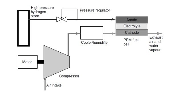
Image 1: Schematic of a fuel cell system
Image source: James Larminie, Andrew Dicks (Fuel Cell Systems Explained)

The simplest type of pressurized PEM fuel cell is that in which the hydrogen gas comes from a high-pressure cylinder. In this design only the air has to be compressed; the hydrogen gas is fed from a pressurized container, and thus it’s compression ‘comes free’. This method of feeding hydrogen to the anode is known as deadening; implying there is no venting or circulation of the gas – it is entirely consumed by the cell.

However, the compressor for the air must be driven by an electric motor, which of course uses up some of the valuable electricity generated by the fuel cell. Typically, for a 100kW system the power consumption will be about 20% of the fuel cell power. As in ICEs, for optimal efficiency the compressed air also needs to be cooled before entry into the PEM cell.

Balancing the pressure to optimize performance

As this is a young evolving technology the reliability and durability of these “supercharged” fuel cells need to be tested and developed if it is to be widely adopted. Hence there is considerable research and development taking place to improve the performance and lifespan.

Testing under controlled conditions is an important step towards the viability and uptake of fuel cells. Detailed measurement data is crucial as input information to create models of the fuel cell operation. Yet, in spite of widespread interest, suitable measurement techniques are still only in the process of being developed.

Typically the PEM fuel cell operates at pressures ranging from near ambient to about 3 bar and at temperatures between 50 and 90°C. High power density is achieved at higher operating pressures but the net system efficiency may be lower on account of the power needed to compress the air. Higher air temperatures also increase power density, but may pose a significant challenge for water and heat management, especially at lower operating pressures.

Therefore selection of operating temperature and pressure of the automotive PEM fuel cell system must be based on (a) high net system efficiency, (b) small component size, and (c) neutral or positive water balance so that the vehicle does not have to carry an on-board reservoir.

The increase in power resulting from operating a PEM fuel cell at higher pressure is mainly the result of the reduction in the cathode activation overvoltage, because the increased pressure raises the exchange current density, which has the apparent effect of lifting the open circuit voltage (OCV), as described by the Nernst equation.

However, as previously mentioned this supercharging comes at the expense of the power that the pressurized fuel cell produces, hence the importance of balancing the pressure to the requirements of the specific fuel cell. As with ICE boost pressures, this can only be done by taking accurate pressure measurements using high quality pressure sensors that are painstakingly calibrated to the environment.

These pressure measurements, recorded with laboratory grade sensors supplied by STS, are then compared to the fuel stack outputs to minimize the parasitic losses while optimizing the gains in electrical output.

As automotive hydrogen fuel cell technology matures and data collected from real-world trials is used to produce predictive models, engineers and researchers will no doubt gain a better understanding of the complex inter-relationship between, temperature, pressure and efficiency: But in the meantime this research will rely heavily on quality sensors recording accurate data.

The turbocharger succumbs to the pressures of energy conservation

The turbocharger succumbs to the pressures of energy conservation

For many years turbochargers were only found on expensive sports cars and diesel powered engines, but emissions regulations changed the way the world viewed forced induction. Although at the core was still the quest to improve performance, now manufacturers were looking at restoring performance and driveability to downsized fuel-sippingengines. So in the 21stCentury, almost everything from the little 999 cm3 Ford Ecoboost to the latest Ferrari’s all gained shiny new turbo technology.

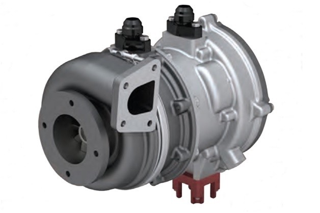
But almost as soon as the tech came into its own it seems set to become redundant, upstaged by the new eCharger. Already Audi’s fitted this to the series production SQ7 and will be rolling out the technology to future production vehicles as 48 Volt electrification gains traction.

The key advantage to the electrically driven supercharger is that, as with turbochargers, there are no parasitic losses; but unlike most turbo’s there’s no turbo lag either and no need for a wastegate. The powerful electric motor can spool up the impeller to 70,000 rpm in less than a second, which eliminates turbo lag.

This naturally improves driveability and reduces consumption and emissions by between 7 and 20 percent when the device is used on a vehicle equipped with regenerative braking, which captures the car’s kinetic energy and turns it into electricity.

Pressure is key to unlocking the eCharger’s performance

Electronically controlled, the eCharger can be mapped to optimize engine performance while maximizing the energy recovered from the exhaust gas, but in order to achieve this Utopia, engineers need to create a map of the boost the engine requires by measuring manifold pressures at various engine loads and speeds. This can only be done with the aid of top quality pressure sensors.

As with any super/ turbo-charger, it’s important that the unit is matched to the engine’s requirements: Failing to do this, will either starve the engine or result in unnecessary electrical power consumption.

Being a maturing technology, not much research and testing data is available to engineers wishing to explore the boundaries of eCharge superchargers. Although fluid dynamics and electrical engineering can provide good foundations from which to build, it’s still vital that theories are validated under real-world test conditions.

In order to qualify the performance, once the baseline eCharger has been selected, the vehicle is equipped with extremely accurate pressure sensors that are readily calibrated and provide precise readings over a wide range of manifold boost pressures and temperatures. These sensors must also be resistant to vibration and chemical degradation.

Both on the engine dynamometer as well as road testing, throttle position/ engine speed/ Manifold air Pressure and temperatures are continuously recorded to ascertain the interrelationship of these key inputs.

From this information, engineers are able to verify that the correct eCharger configuration has been selected whilst at the same time ensuring that the closed loop engine management controls are able to correctly respond to the key variables.

The result of getting this right delivers a vehicle, such as the SQ7, which has stunning performance, drive ability and fuel consumption whilst still meeting future global emissions regulations.

Accurate pressure measurement is critical to safe, cost-effective, motor vehicle development

Accurate pressure measurement is critical to safe, cost-effective, motor vehicle development

The principle of hydraulic power to carry out work has been around since ancient Egyptian times, but as systems have evolved, so too have the tools required to design and develop these sophisticated, often critical circuits.

From the earliest manometer invented by Evangelista Torricelli in the 1600’s to the mechanical Bourdon gauge and finally today, the piezoresistive pressure transducer, developers have always sought the best equipment to measure pressures and optimize the design. And in recent times automotive engineers, in particular, have come to rely on these high-quality, accurate pressure sensors when carrying out vehicle testing and development.

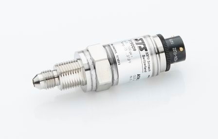
These current pressure transducers are typically capable of recording full-scale deflections from about 350 mbar to 700 bar under sustained temperatures ranging from -40OC to 150°C; and best of all, quality sensors such as those produced by STS, are capable of a hysteresis and repeatability of typically around 0.001%!

Image 1: High precision pressure transmitter ATM.1ST with accuracy of up to 0.05% FS

High-quality pressure sensors are used in the development of key automotive systems.

This level of repeatability is critical in the design and development of cooling and fuel delivery systems, amongst others. During development, designers rely on stable pressure measuring equipment to accurately record information so that the effect of even the smallest of design changes can be documented without concerns that the sensor is incapable of repeatable results.

In a recent redesign of an engine cooling system to take advantage of the reduced parasitic losses made possible through electrification, the engineering team at a luxury OEM was initially faced with a pressure drop across the pump of around 250kPa. Before a redesign of the new electric pump was possible, accurate pressure measurements had to be recorded allowing engineers the opportunity to identify the problem. After studying the results logged by the array of pressure sensors the design was modified, reducing the drop to less than 100kPa and cutting the parasitic losses by 500W.

And although electrification and electronic controls are playing increasingly significant roles in vehicle systems, hydraulic pressure is still relied upon to guarantee smooth operation of many critical circuits.

By way of example, during the development of an automatic transmission, port line pressures have to be measured in real time and then compared to design norms to confirm that design parameters are being met. At the same time, shift times and quality are measured and subjectively evaluated to ensure drivability and performance meet customer requirements.

Notwithstanding the value of high-quality pressure sensors in recording valuable data during testing and development, in industrializing future technologies these tools can also significantly reduce design costs.

Pressure sensors make sure future technologies measure up to expectations.

In an attempt to improve the performance of severely downsized engines, manufacturers are taking advantage of the additional power 48V electrification offers, by replacing the turbocharger with an electrical supercharger.

Being a maturing technology, not much research and testing data are available to engineers wishing to optimize eCharge superchargers. Although fluid dynamics and electrical engineering provide a sound platform from which to build, it’s still vital that theories are validated under real-world test conditions.

To achieve this, manifold pressures must be mapped to optimize engine performance while maximizing the energy recovered from the exhaust gas. For this, extremely accurate pressure sensors that provide precise readings over a wide range of manifold boost pressures and temperatures are required. These sensors must also be resistant to vibration and chemical degradation.

And while manufacturers around the world continue to carry out research into electric vehicles, several groups are considering ways to harness hydrogen to generate electricity instead of relying on storage batteries.

Hydrogen fuel cells employing proton exchange membranes, also known as polymer electrolyte membrane (PEM) fuel cells (PEMFC), have already seen limited series production in vehicles such as Toyota’s Mirai.

Although small PEM fuel cells commonly operate at normal air pressure, higher powered fuel cells, of 10kW or more, usually run at elevated pressures. As with conventional Internal Combustion Engines, the purpose of increasing the pressure in a fuel stack is to increase the specific power by extracting more power out of the same size cell.

Typically the PEM fuel cell operates at pressures ranging from near atmospheric to about 3Bar, and at temperatures between 50 and 90°C. While higher power densities made possible by increasing the operating pressure, the net system efficiency may be lower due to the power needed to compress the air; hence the importance of balancing the pressure to the requirements of the particular fuel cell.

As with ICE boost pressures, this can only be done by taking accurate pressure measurements using high-quality pressure sensors. These measurements are then compared to the fuel stack outputs to minimize the parasitic losses while optimizing the gains in electrical output.

So, irrespective of the course the automotive industry chooses for future technologies, accurate pressure sensors will remain key to the development of safe and efficient vehicles.

Subscribe To Our Newsletter

Join our mailing list to receive the latest news and updates from our team.

You have Successfully Subscribed!